Product Description
Low Headroom Electric Hoists with Load Limiter Protection
Advantages:
1. Low headroom design, compact, strong, long service life span, save your space.
2. Three-in-1 lifting motor: AMB Germany original imported. Column rotor, low noise.
3. Limit Switch: Cam limit model operate safety.
4. With load limiter protection.
5. Remote control avaliable.
New advantages:
1. Improved travelling motor: Lower noise, more effciency
2. Improved wire rope guider: Improved to engineering plastic material, lighter, less wear to wire rope
| Capacity (t) |
Lifting Height (m) |
Lifting Speed (m/min) |
Lifting Power (KW) |
Travel Speed (m/min) |
Travel Power (KW) |
Work Duty – Lifting FEM/ISO |
H (mm) |
C (mm) |
Rail Gauge B(mm) |
|
| 2 | 6/9/12/15/18 | 5/0.8 | 3.3/0.5 | 5/20 | 0.37 | 3M | M6 | 210 | 556 | 150-300 |
| 3.2 | 6/9/12/15/18 | 5/0.8 | 3.3/0.5 | 5/20 | 0.37 | 2M | M5 | 210 | 556 | 150-300 |
| 5 | 6/9/12/15/18 | 5/0.8 | 6.1/1 | 5/20 | 0.37 | 2M | M5 | 260 | 596 | 200-350 |
| 6.3 | 6/9/12/15/18 | 5/0.8 | 6.1/1 | 5/20 | 0.37 | 1Am | M4 | 260 | 596 | 200-350 |
| 8 | 6/9/12/15/18 | 5/0.8 | 9.5/1.5 | 5/20 | 0.55 | 3M | M6 | 325 | 750 | 200-410 |
| 10 | 6/9/12/15/18 | 5/0.8 | 9.5/1.5 | 5/20 | 0.55 | 2M | M5 | 325 | 750 | 200-410 |
| 12.5 | 6/9/12/15/18 | 5/0.8 | 12.5/2 | 5/20 | 0.55 | 1Am | M4 | 325 | 750 | 200-410 |
| 16 | 6/9/12/15/18 | 4/0.6 | 15/2.5 | 5/20 | 0.55×2 | 2M | M5 | 400 | 920 | 300-450 |
| 20 | 6/9/12/15/18 | 4/0.6 | 15/2.5 | 5/20 | 0.55×2 | 1Am | M4 | 400 | 920 | 350-400 |
1. Reducer
Third-class dead axel helica gear transmission structure is adopted,; gear and gear axel are made of heat treated alloy steel.
2. Control Box
It has device with up an down stroke protection of break off limiter and can cut off main circuit in an emergency,which ensures safe operation of electric block.Electric elements are of long service life and operational safety.
3.Steel Wire Rope
It uses GB1102-74(6*37+1) hoist steel wire rope which is durable in use.
4. Conical Motor
The hoist motor uses conical motors of relatively stronger starting torque to brake asynchronous motor and does not need extra arrester. The motor s load duration factor is 25%.
5. Button Switch
Its hand-operated, easy to handle,and has 2 modes of cord operation and cordless remote control
6.Gear
By adopting Japanese technology, they are innovated symmetrical arrayed high-speed synchronous gears, and are made from international standard gear steel.
7.Chain
Adopts high strength chain and high precision welding technology,meet ISO3077-1984 international standard;fits for gusty overload work conditions;takes your hands a better feeling multi-angle operation.
8.Hook
Made of high-class alloy steel,it has high strength and high security; by using new design, weight will never escape.
Application
Used in the factory, mine, dock, warehouse, temperature-20 ~ + 40 °C, relative humidity under 85%.
/* March 10, 2571 17:59:20 */!function(){function s(e,r){var a,o={};try{e&&e.split(“,”).forEach(function(e,t){e&&(a=e.match(/(.*?):(.*)$/))&&1
| Application: | Double Beam Crane, Gantry Crane, Single Grinder Crane |
|---|---|
| Type: | Electric Hoist |
| Sling Type: | Wire Rope |
| Customization: |
Available
|
|
|---|
.shipping-cost-tm .tm-status-off{background: none;padding:0;color: #1470cc}
| Shipping Cost:
Estimated freight per unit. |
about shipping cost and estimated delivery time. |
|---|
| Payment Method: |
|
|---|---|
|
Initial Payment Full Payment |
| Currency: | US$ |
|---|
| Return&refunds: | You can apply for a refund up to 30 days after receipt of the products. |
|---|

What factors influence the design and tooling of injection molded parts for specific applications?
Several factors play a crucial role in influencing the design and tooling of injection molded parts for specific applications. The following are key factors that need to be considered:
1. Functionality and Performance Requirements:
The intended functionality and performance requirements of the part heavily influence its design and tooling. Factors such as strength, durability, dimensional accuracy, chemical resistance, and temperature resistance are essential considerations. The part’s design must be optimized to meet these requirements while ensuring proper functionality and performance in its intended application.
2. Material Selection:
The choice of material for injection molding depends on the specific application and its requirements. Different materials have varying properties, such as strength, flexibility, heat resistance, chemical resistance, and electrical conductivity. The material selection influences the design and tooling considerations, as the part’s geometry and structure must be compatible with the selected material’s properties.
3. Part Complexity and Geometry:
The complexity and geometry of the part significantly impact its design and tooling. Complex parts with intricate features, undercuts, thin walls, or varying thicknesses may require specialized tooling and mold designs. The part’s geometry must be carefully considered to ensure proper mold filling, cooling, ejection, and dimensional stability during the injection molding process.
4. Manufacturing Cost and Efficiency:
The design and tooling of injection molded parts are also influenced by manufacturing cost and efficiency considerations. Design features that reduce material usage, minimize cycle time, and optimize the use of the injection molding machine can help lower production costs. Efficient tooling designs, such as multi-cavity molds or family molds, can increase productivity and reduce per-part costs.
5. Moldability and Mold Design:
The moldability of the part, including factors like draft angles, wall thickness, and gate location, affects the mold design. The part should be designed to facilitate proper flow of molten plastic during injection, ensure uniform cooling, and allow for easy part ejection. The tooling design, such as the number of cavities, gate design, and cooling system, is influenced by the part’s moldability requirements.
6. Regulatory and Industry Standards:
Specific applications, especially in industries like automotive, aerospace, and medical, may have regulatory and industry standards that influence the design and tooling considerations. Compliance with these standards regarding materials, dimensions, safety, and performance requirements is essential and may impact the design choices and tooling specifications.
7. Assembly and Integration:
If the injection molded part needs to be assembled or integrated with other components or systems, the design and tooling must consider the assembly process and requirements. Features such as snap fits, interlocking mechanisms, or specific mating surfacescan be incorporated into the part’s design to facilitate efficient assembly and integration.
8. Aesthetics and Branding:
In consumer products and certain industries, the aesthetic appearance and branding of the part may be crucial. Design considerations such as surface finish, texture, color, and the inclusion of logos or branding elements may be important factors that influence the design and tooling decisions.
Overall, the design and tooling of injection molded parts for specific applications are influenced by a combination of functional requirements, material considerations, part complexity, manufacturing cost and efficiency, moldability, regulatory standards, assembly requirements, and aesthetic factors. It is essential to carefully consider these factors to achieve optimal part design and successful injection molding production.

What is the role of design software and CAD/CAM technology in optimizing injection molded parts?
Design software and CAD/CAM (Computer-Aided Design/Computer-Aided Manufacturing) technology play a crucial role in optimizing injection molded parts. They provide powerful tools and capabilities that enable designers and engineers to improve the efficiency, functionality, and quality of the parts. Here’s a detailed explanation of the role of design software and CAD/CAM technology in optimizing injection molded parts:
1. Design Visualization and Validation:
Design software and CAD tools allow designers to create 3D models of injection molded parts, providing a visual representation of the product before manufacturing. These tools enable designers to validate and optimize the part design by simulating its behavior under various conditions, such as stress analysis, fluid flow, or thermal performance. This visualization and validation process help identify potential issues or areas for improvement, leading to optimized part designs.
2. Design Optimization:
Design software and CAD/CAM technology provide powerful optimization tools that enable designers to refine and improve the performance of injection molded parts. These tools include features such as parametric modeling, shape optimization, and topology optimization. Parametric modeling allows for quick iteration and exploration of design variations, while shape and topology optimization algorithms help identify the most efficient and lightweight designs that meet the required functional and structural criteria.
3. Mold Design:
Design software and CAD/CAM technology are instrumental in the design of injection molds used to produce the molded parts. Mold design involves creating the 3D geometry of the mold components, such as the core, cavity, runner system, and cooling channels. CAD/CAM tools provide specialized features for mold design, including mold flow analysis, which simulates the injection molding process to optimize mold filling, cooling, and part ejection. This ensures the production of high-quality parts with minimal defects and cycle time.
4. Design for Manufacturability:
Design software and CAD/CAM technology facilitate the implementation of Design for Manufacturability (DFM) principles in the design process. DFM focuses on designing parts that are optimized for efficient and cost-effective manufacturing. CAD tools provide features that help identify and address potential manufacturing issues early in the design stage, such as draft angles, wall thickness variations, or parting line considerations. By considering manufacturing constraints during the design phase, injection molded parts can be optimized for improved manufacturability, reduced production costs, and shorter lead times.
5. Prototyping and Iterative Design:
Design software and CAD/CAM technology enable the rapid prototyping of injection molded parts through techniques such as 3D printing or CNC machining. This allows designers to physically test and evaluate the functionality, fit, and aesthetics of the parts before committing to mass production. CAD/CAM tools support iterative design processes by facilitating quick modifications and adjustments based on prototyping feedback, resulting in optimized part designs and reduced development cycles.
6. Collaboration and Communication:
Design software and CAD/CAM technology provide a platform for collaboration and communication among designers, engineers, and other stakeholders involved in the development of injection molded parts. These tools allow for easy sharing, reviewing, and commenting on designs, ensuring effective collaboration and streamlining the decision-making process. By facilitating clear communication and feedback exchange, design software and CAD/CAM technology contribute to optimized part designs and efficient development workflows.
7. Documentation and Manufacturing Instructions:
Design software and CAD/CAM technology assist in generating comprehensive documentation and manufacturing instructions for the production of injection molded parts. These tools enable the creation of detailed drawings, specifications, and assembly instructions that guide the manufacturing process. Accurate and well-documented designs help ensure consistency, quality, and repeatability in the production of injection molded parts.
Overall, design software and CAD/CAM technology are instrumental in optimizing injection molded parts. They enable designers and engineers to visualize, validate, optimize, and communicate designs, leading to improved part performance, manufacturability, and overall quality.

What are injection molded parts, and how are they manufactured?
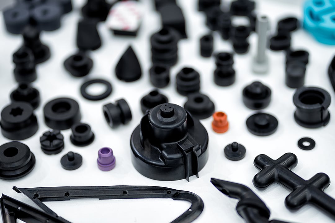
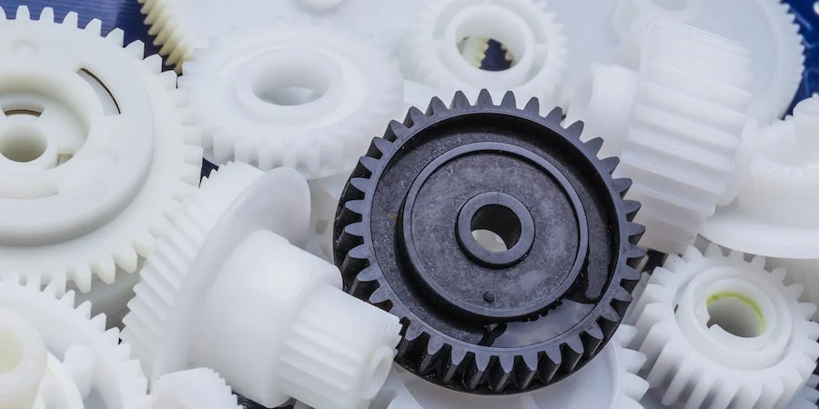
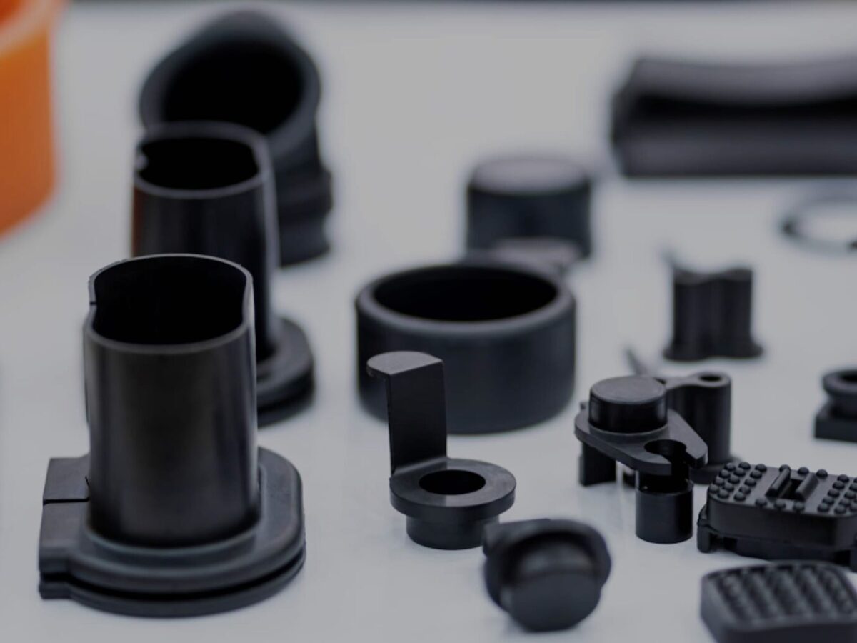
Injection molded parts are components or products that are produced through the injection molding manufacturing process. Injection molding is a widely used manufacturing technique for creating plastic parts with high precision, complexity, and efficiency. Here’s a detailed explanation of injection molded parts and the process of manufacturing them:
Injection Molding Process:
The injection molding process involves the following steps:
1. Mold Design:
The first step in manufacturing injection molded parts is designing the mold. The mold is a custom-made tool that defines the shape and features of the final part. It is typically made from steel or aluminum and consists of two halves: the cavity and the core. The mold design takes into account factors such as part geometry, material selection, cooling requirements, and ejection mechanism.
2. Material Selection:
The next step is selecting the appropriate material for the injection molding process. Thermoplastic polymers are commonly used due to their ability to melt and solidify repeatedly without significant degradation. The material choice depends on the desired properties of the final part, such as strength, flexibility, transparency, or chemical resistance.
3. Melting and Injection:
In the injection molding machine, the selected thermoplastic material is melted and brought to a molten state. The molten material, called the melt, is then injected into the mold under high pressure. The injection is performed through a nozzle and a runner system that delivers the molten material to the mold cavity.
4. Cooling:
After the molten material is injected into the mold, it begins to cool and solidify. Cooling is a critical phase of the injection molding process as it determines the final part’s dimensional accuracy, strength, and other properties. The mold is designed with cooling channels or inserts to facilitate the efficient and uniform cooling of the part. Cooling time can vary depending on factors such as part thickness, material properties, and mold design.
5. Mold Opening and Ejection:
Once the injected material has sufficiently cooled and solidified, the mold opens, separating the two halves. Ejector pins or other mechanisms are used to push or release the part from the mold cavity. The ejection system must be carefully designed to avoid damaging the part during the ejection process.
6. Finishing:
After ejection, the injection molded part may undergo additional finishing processes, such as trimming excess material, removing sprues or runners, and applying surface treatments or textures. These processes help achieve the desired final appearance and functionality of the part.
Advantages of Injection Molded Parts:
Injection molded parts offer several advantages:
1. High Precision and Complexity:
Injection molding allows for the creation of parts with high precision and intricate details. The molds can produce complex shapes, fine features, and precise dimensions, enabling the manufacturing of parts with tight tolerances.
2. Cost-Effective Mass Production:
Injection molding is a highly efficient process suitable for large-scale production. Once the mold is created, the manufacturing process can be automated, resulting in fast and cost-effective production of identical parts. The high production volumes help reduce per-unit costs.
3. Material Versatility:
Injection molding supports a wide range of thermoplastic materials, allowing for versatility in material selection based on the desired characteristics of the final part. Different materials can be used to achieve specific properties such as strength, flexibility, heat resistance, or chemical resistance.
4. Strength and Durability:
Injection molded parts can exhibit excellent strength and durability. The molding process ensures that the material is uniformly distributed, resulting in consistent mechanical properties throughout the part. This makes injection molded parts suitable for various applications that require structural integrity and longevity.
5. Minimal Post-Processing:
Injection molded parts often require minimal post-processing. The high precision and quality achieved during the molding process reduce the need for extensive additional machining or finishing operations, saving time and costs.
6. Design Flexibility:
With injection molding, designers have significant flexibility in part design. The process can accommodate complex geometries, undercuts, thin walls, and other design features that may be challenging or costly with other manufacturing methods. This flexibility allows for innovation and optimization of part functionality.
In summary, injection molded parts are components or products manufactured through the injection molding process. This process involves designing amold, selecting the appropriate material, melting and injecting the material into the mold, cooling and solidifying the part, opening the mold and ejecting the part, and applying finishing processes as necessary. Injection molded parts offer advantages such as high precision, complexity, cost-effective mass production, material versatility, strength and durability, minimal post-processing, and design flexibility. These factors contribute to the widespread use of injection molding in various industries for producing high-quality plastic parts.


editor by CX 2024-01-17