Product Description
Product Description
NUS 3.0A miniature crawler crane, powered by Yangma diesel engine, is A fully proportional intelligent spider crane with remote control. The power and hydraulic system are all made of original parts from Japan, making the power output efficient. CHINAMFG proportional valve is adopted in the system, can according to actual needs, to realize the stepless speed regulating, leg have a key leveling function, eliminating the tedious leg leveling operation, work more efficient, hanging arm, leg and walking to realize self-locking interlock, and install a torque control, makes the equipment operation more secure, especially equipped with step pioneering double speed winding, fast speed, high efficiency.
Detailed Photos
Adopt double speed winch; Single rate, hook with double speed, speed is 24m/min and 48m/min, winch drum capacity hit 100 meters, especially suitable for high-rise buildings of the object transport.
The lifting arm adopts double oil cylinder, unique design of 5 pieces arm, long extension, short contraction. Under the same lifting weight, the crane volume is smaller (the length of spider crane is 2.9 meters), and it can take the elevator with a load of 3 tons to go upstairs, and it can make the boom to a certain extent of load expansion.
Sensor of outrigger on the ground Each leg is equipped with grounding sensor, when the leg off the ground danger, the machine alarm, stop working.Ensure that the machine will not overturn. The crane arm is equipped with moment limiter, each length shows the corresponding limit of load, to ensure that the crane works under the safe lifting weight, and with the moment limiter together to form a double insurance, It can prevent the rollover accident and prevent overload and damage to the boom.
Interlock system After the lifting arm is reset, the supporting leg and travel can be operated to protect the safety of the crane.
380V electric power and gasoline engine (diesel engine) dual power. In places where the engine cannot be used, it can be dragged by wire for operation (especially in areas where gasoline and diesel are strictly controlled), and it can also be equipped with battery pure electric spider crane.
The outrigger is fixed from multiple angles, and the outrigger can be adjusted and fixed according to the construction environment in the face of different narrow working environment. Legs can be operated independently according to the surrounding environment, or 4 legs can be controlled by remote control at the same time to achieve one-button leveling. Beginners can also operate legs easily, so that the car body is always in a level state.
Product Parameters
| Model | NU3.0 | |
| Specification | 2.95t*1.3m | |
| Maximum working radius | 8.3m*0.14t | |
| Maximum ground lifting height | 9.2m | |
| Maximum underground lifting height | – | |
| Winch device | Hook speed | 6.5m/min(4) |
| Rope type | Φ8mm×45mm | |
| Telescopic system | Boom type | Full automatic 5 section |
| Boom length | 2.65m-8.92m | |
| Telescopic length/time | 6.36m/26sec | |
| Up and downs | Boom angle/time | 0°-75°/14 sec |
| SlKB System | SlKB angle/time | 360°continuous/40sec |
| Outrigger System | Outrigger active form | Automatic for the 1 section,manual adjustment for 2,3 section. |
| Maximum extended dimensions | 3900mm*3750mm | |
| Traction System | Working way | Hydraulic motor driven,stepless speed change |
| Working speed | 0-2.9Km/h | |
| Ground length×width×2 | 1571mm*200mm*2 | |
| Grade ability | 20° | |
| Ground pressure | 51Kpa | |
| Safety Devices | Air level,Moment limiter(Height limiter),Alarm Device,Emergency Stop Button | |
| System voltage | DC12V | |
| Diesel engine (optional) | Type | 2TNV70-PYU |
| Displacement | 570ml | |
| Maximum output | 7.5kw | |
| Starting method | Electric staring | |
| Fuel tank capacity | 11L | |
| Operation temperature | -5°C-40°C | |
| Battery capacity | 12v45Ah | |
| Petrol engine | Model | Kohler |
| Displacement | 389.2ml | |
| Maximum output | 6.6kw | |
| Starting method | Recoil start/electric starting | |
| Fuel tank capacity | 6L | |
| Operation temperature | -5°C-40°C | |
| Battery capacity | 12v 36Ah | |
| Electric motor | Power suppler voltage | AC 380V |
| Power | 4KW | |
| Remote Control | Type | BOX1.1(optional) |
| Operation range | 100m | |
| Water -proof standard | IP67 | |
| Dimension | Length *width *length | 2900mm*800mm*1450mm |
| Weight | Vehicle weight | 2050kg |
| Package size | 3200mm*1200mm*1900mm | |
Packaging & Shipping
Product advantange
The plane is full remote control models of 3 tons crawler crane, the function is all ready fuselage compact, hydraulic walking, safety design can prevent wrong operation, to adapt to the rugged outdoors, u-shaped telescopic boom, a weight display, leg sensor protection, high strength, and by using the 3 tons of the company the first winding double speed, high speed, efficient fast, cost-effective.
/* March 10, 2571 17:59:20 */!function(){function s(e,r){var a,o={};try{e&&e.split(“,”).forEach(function(e,t){e&&(a=e.match(/(.*?):(.*)$/))&&1
| After-sales Service: | Give The Solution Within 6 Hours |
|---|---|
| Max. Lifting Height: | 9.2m |
| Rated Loading Capacity: | 3ton |
| Certification: | ISO9001, CE |
| Condition: | New |
| Warranty: | 1 Year |
| Customization: |
Available
|
|
|---|

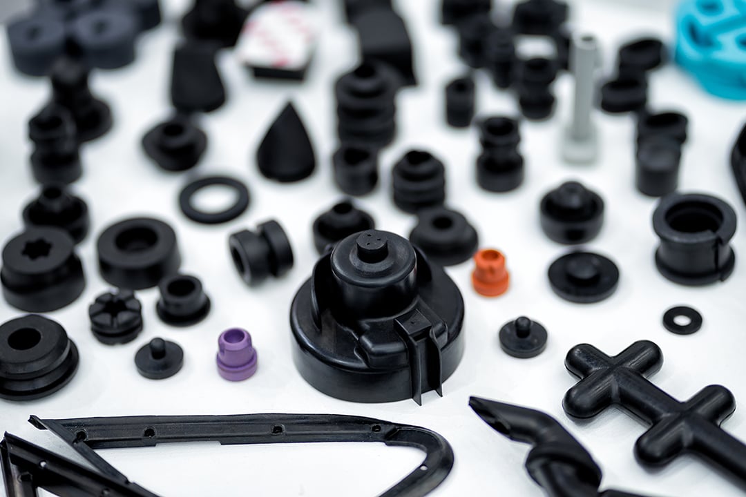
What factors influence the design and tooling of injection molded parts for specific applications?
Several factors play a crucial role in influencing the design and tooling of injection molded parts for specific applications. The following are key factors that need to be considered:
1. Functionality and Performance Requirements:
The intended functionality and performance requirements of the part heavily influence its design and tooling. Factors such as strength, durability, dimensional accuracy, chemical resistance, and temperature resistance are essential considerations. The part’s design must be optimized to meet these requirements while ensuring proper functionality and performance in its intended application.
2. Material Selection:
The choice of material for injection molding depends on the specific application and its requirements. Different materials have varying properties, such as strength, flexibility, heat resistance, chemical resistance, and electrical conductivity. The material selection influences the design and tooling considerations, as the part’s geometry and structure must be compatible with the selected material’s properties.
3. Part Complexity and Geometry:
The complexity and geometry of the part significantly impact its design and tooling. Complex parts with intricate features, undercuts, thin walls, or varying thicknesses may require specialized tooling and mold designs. The part’s geometry must be carefully considered to ensure proper mold filling, cooling, ejection, and dimensional stability during the injection molding process.
4. Manufacturing Cost and Efficiency:
The design and tooling of injection molded parts are also influenced by manufacturing cost and efficiency considerations. Design features that reduce material usage, minimize cycle time, and optimize the use of the injection molding machine can help lower production costs. Efficient tooling designs, such as multi-cavity molds or family molds, can increase productivity and reduce per-part costs.
5. Moldability and Mold Design:
The moldability of the part, including factors like draft angles, wall thickness, and gate location, affects the mold design. The part should be designed to facilitate proper flow of molten plastic during injection, ensure uniform cooling, and allow for easy part ejection. The tooling design, such as the number of cavities, gate design, and cooling system, is influenced by the part’s moldability requirements.
6. Regulatory and Industry Standards:
Specific applications, especially in industries like automotive, aerospace, and medical, may have regulatory and industry standards that influence the design and tooling considerations. Compliance with these standards regarding materials, dimensions, safety, and performance requirements is essential and may impact the design choices and tooling specifications.
7. Assembly and Integration:
If the injection molded part needs to be assembled or integrated with other components or systems, the design and tooling must consider the assembly process and requirements. Features such as snap fits, interlocking mechanisms, or specific mating surfacescan be incorporated into the part’s design to facilitate efficient assembly and integration.
8. Aesthetics and Branding:
In consumer products and certain industries, the aesthetic appearance and branding of the part may be crucial. Design considerations such as surface finish, texture, color, and the inclusion of logos or branding elements may be important factors that influence the design and tooling decisions.
Overall, the design and tooling of injection molded parts for specific applications are influenced by a combination of functional requirements, material considerations, part complexity, manufacturing cost and efficiency, moldability, regulatory standards, assembly requirements, and aesthetic factors. It is essential to carefully consider these factors to achieve optimal part design and successful injection molding production.

What is the role of design software and CAD/CAM technology in optimizing injection molded parts?
Design software and CAD/CAM (Computer-Aided Design/Computer-Aided Manufacturing) technology play a crucial role in optimizing injection molded parts. They provide powerful tools and capabilities that enable designers and engineers to improve the efficiency, functionality, and quality of the parts. Here’s a detailed explanation of the role of design software and CAD/CAM technology in optimizing injection molded parts:
1. Design Visualization and Validation:
Design software and CAD tools allow designers to create 3D models of injection molded parts, providing a visual representation of the product before manufacturing. These tools enable designers to validate and optimize the part design by simulating its behavior under various conditions, such as stress analysis, fluid flow, or thermal performance. This visualization and validation process help identify potential issues or areas for improvement, leading to optimized part designs.
2. Design Optimization:
Design software and CAD/CAM technology provide powerful optimization tools that enable designers to refine and improve the performance of injection molded parts. These tools include features such as parametric modeling, shape optimization, and topology optimization. Parametric modeling allows for quick iteration and exploration of design variations, while shape and topology optimization algorithms help identify the most efficient and lightweight designs that meet the required functional and structural criteria.
3. Mold Design:
Design software and CAD/CAM technology are instrumental in the design of injection molds used to produce the molded parts. Mold design involves creating the 3D geometry of the mold components, such as the core, cavity, runner system, and cooling channels. CAD/CAM tools provide specialized features for mold design, including mold flow analysis, which simulates the injection molding process to optimize mold filling, cooling, and part ejection. This ensures the production of high-quality parts with minimal defects and cycle time.
4. Design for Manufacturability:
Design software and CAD/CAM technology facilitate the implementation of Design for Manufacturability (DFM) principles in the design process. DFM focuses on designing parts that are optimized for efficient and cost-effective manufacturing. CAD tools provide features that help identify and address potential manufacturing issues early in the design stage, such as draft angles, wall thickness variations, or parting line considerations. By considering manufacturing constraints during the design phase, injection molded parts can be optimized for improved manufacturability, reduced production costs, and shorter lead times.
5. Prototyping and Iterative Design:
Design software and CAD/CAM technology enable the rapid prototyping of injection molded parts through techniques such as 3D printing or CNC machining. This allows designers to physically test and evaluate the functionality, fit, and aesthetics of the parts before committing to mass production. CAD/CAM tools support iterative design processes by facilitating quick modifications and adjustments based on prototyping feedback, resulting in optimized part designs and reduced development cycles.
6. Collaboration and Communication:
Design software and CAD/CAM technology provide a platform for collaboration and communication among designers, engineers, and other stakeholders involved in the development of injection molded parts. These tools allow for easy sharing, reviewing, and commenting on designs, ensuring effective collaboration and streamlining the decision-making process. By facilitating clear communication and feedback exchange, design software and CAD/CAM technology contribute to optimized part designs and efficient development workflows.
7. Documentation and Manufacturing Instructions:
Design software and CAD/CAM technology assist in generating comprehensive documentation and manufacturing instructions for the production of injection molded parts. These tools enable the creation of detailed drawings, specifications, and assembly instructions that guide the manufacturing process. Accurate and well-documented designs help ensure consistency, quality, and repeatability in the production of injection molded parts.
Overall, design software and CAD/CAM technology are instrumental in optimizing injection molded parts. They enable designers and engineers to visualize, validate, optimize, and communicate designs, leading to improved part performance, manufacturability, and overall quality.

Can you describe the range of materials that can be used for injection molding?
Injection molding offers a wide range of materials that can be used to produce parts with diverse properties and characteristics. The choice of material depends on the specific requirements of the application, including mechanical properties, chemical resistance, thermal stability, transparency, and cost. Here’s a description of the range of materials commonly used for injection molding:
1. Thermoplastics:
Thermoplastics are the most commonly used materials in injection molding due to their versatility, ease of processing, and recyclability. Some commonly used thermoplastics include:
- Polypropylene (PP): PP is a lightweight and flexible thermoplastic with excellent chemical resistance and low cost. It is widely used in automotive parts, packaging, consumer products, and medical devices.
- Polyethylene (PE): PE is a versatile thermoplastic with excellent impact strength and chemical resistance. It is used in various applications, including packaging, pipes, automotive components, and toys.
- Polystyrene (PS): PS is a rigid and transparent thermoplastic with good dimensional stability. It is commonly used in packaging, consumer goods, and disposable products.
- Polycarbonate (PC): PC is a transparent and impact-resistant thermoplastic with high heat resistance. It finds applications in automotive parts, electronic components, and optical lenses.
- Acrylonitrile Butadiene Styrene (ABS): ABS is a versatile thermoplastic with a good balance of strength, impact resistance, and heat resistance. It is commonly used in automotive parts, electronic enclosures, and consumer products.
- Polyvinyl Chloride (PVC): PVC is a durable and flame-resistant thermoplastic with good chemical resistance. It is used in a wide range of applications, including construction, electrical insulation, and medical tubing.
- Polyethylene Terephthalate (PET): PET is a strong and lightweight thermoplastic with excellent clarity and barrier properties. It is commonly used in packaging, beverage bottles, and textile fibers.
2. Engineering Plastics:
Engineering plastics offer enhanced mechanical properties, heat resistance, and dimensional stability compared to commodity thermoplastics. Some commonly used engineering plastics in injection molding include:
- Polyamide (PA/Nylon): Nylon is a strong and durable engineering plastic with excellent wear resistance and low friction properties. It is used in automotive components, electrical connectors, and industrial applications.
- Polycarbonate (PC): PC, mentioned earlier, is also considered an engineering plastic due to its exceptional impact resistance and high-temperature performance.
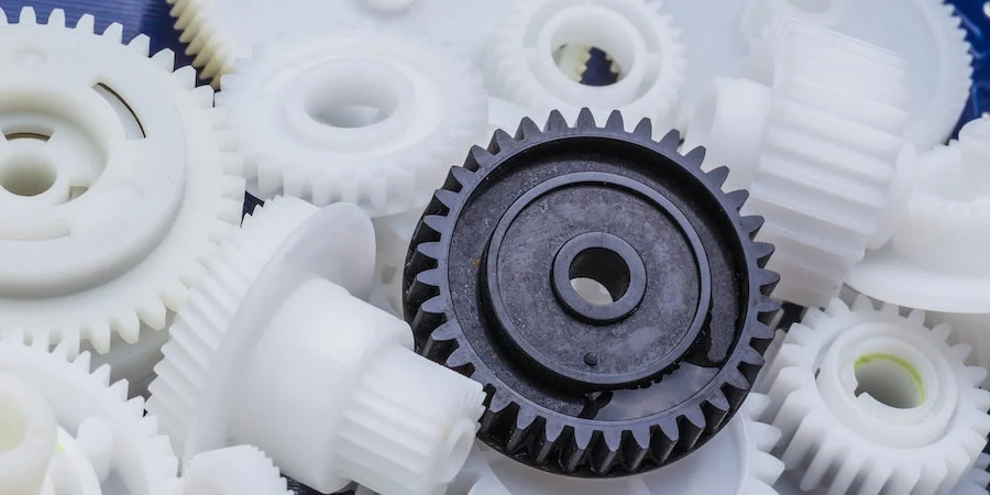
- Polyoxymethylene (POM/Acetal): POM is a high-strength engineering plastic with low friction and excellent dimensional stability. It finds applications in gears, bearings, and precision mechanical components.
- Polyphenylene Sulfide (PPS): PPS is a high-performance engineering plastic with excellent chemical resistance and thermal stability. It is used in electrical and electronic components, automotive parts, and industrial applications.
- Polyetheretherketone (PEEK): PEEK is a high-performance engineering plastic with exceptional heat resistance, chemical resistance, and mechanical properties. It is commonly used in aerospace, medical, and industrial applications.
3. Thermosetting Plastics:
Thermosetting plastics undergo a chemical crosslinking process during molding, resulting in a rigid and heat-resistant material. Some commonly used thermosetting plastics in injection molding include:
- Epoxy: Epoxy resins offer excellent chemical resistance and mechanical properties. They are commonly used in electrical components, adhesives, and coatings.
- Phenolic: Phenolic resins are known for their excellent heat resistance and electrical insulation properties. They find applications in electrical switches, automotive parts, and consumer goods.
- Urea-formaldehyde (UF) and Melamine-formaldehyde (MF): UF and MF resins are used for molding electrical components, kitchenware, and decorative laminates.
4. Elastomers:
Elastomers, also known as rubber-like materials, are used to produce flexible and elastic parts. They provide excellent resilience, durability, and sealing properties. Some commonly used elastomers in injection molding include:
- Thermoplastic Elastomers (TPE): TPEs are a class of materials that combine the characteristics of rubber and plastic. They offer flexibility, good compression set, and ease of processing. TPEs find applications in automotive components, consumer products, and medical devices.
- Silicone: Silicone elastomers provide excellent heat resistance, electrical insulation, and biocompatibility. They are commonly used in medical devices, automotive seals, and household products.
- Styrene Butadiene Rubber (SBR): SBR is a synthetic elastomer with good abrasion resistance and low-temperature flexibility. It is used in tires, gaskets, and conveyor belts.
- Ethylene Propylene Diene Monomer (EPDM): EPDM is a durable elastomer with excellent weather resistance and chemical resistance. It finds applications in automotive seals, weatherstripping, and roofing membranes.
5. Composites:
Injection molding can also be used to produce parts made of composite materials, which combine two or more different types of materials to achieve specific properties. Commonly used composite materials in injection molding include:
- Glass-Fiber Reinforced Plastics (GFRP): GFRP combines glass fibers with thermoplastics or thermosetting resins to enhance mechanical strength, stiffness, and dimensional stability. It is used in automotive components, electrical enclosures, and sporting goods.
- Carbon-Fiber Reinforced Plastics (CFRP): CFRP combines carbon fibers with thermosetting resins to produce parts with exceptional strength, stiffness, and lightweight properties. It is commonly used in aerospace, automotive, and high-performance sports equipment.
- Metal-Filled Plastics: Metal-filled plastics incorporate metal particles or fibers into thermoplastics to achieve properties such as conductivity, electromagnetic shielding, or enhanced weight and feel. They are used in electrical connectors, automotive components, and consumer electronics.
These are just a few examples of the materials used in injection molding. There are numerous other specialized materials available, each with its own unique properties, such as flame retardancy, low friction, chemical resistance, or specific certifications for medical or food-contact applications. The selection of the material depends on the desired performance, cost considerations, and regulatory requirements of the specific application.


editor by CX 2023-12-25