Product Description
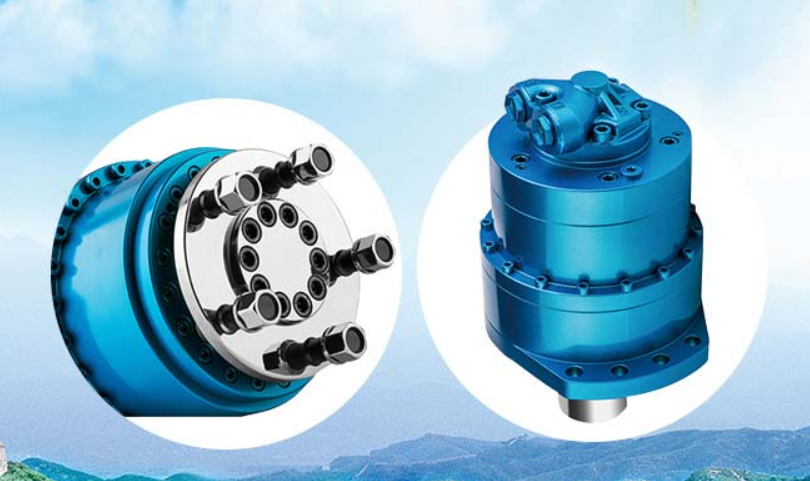
Sauer 51D110 51D160 51D080 Hydraulic Motor
General Description
Series 51 Variable Displacement Motors are bent axis
design units, incorporating spherical pistons.
These motors are designed primarily to be combined
with other products in closed circuit systems to transfer
and control hydraulic power.
Series 51 Motors have a large maximum / minimum
displacement ratio (5 to 1) and high output speed capabilities. SAE flange and cartridge motor configurations
are available.
A complete family of controls and regulators is available to
fulfill the requirements of a wide range of applications.
Motors equipped with controls normally start at maxi-
Front page: Option – hydraulic two-position control
All trademarks in this material are properties of their respective owners.
mum displacement. This provides maximum starting
torque (high acceleration).
The controls may utilize externally or internally supplied
servo pressure. They may be overridden by a pressure
compensator which functions when the motor is op-
erating in motor and pump modes. A defeat option is
available to disable the pressure compensator override
when the motor is running in pump mode.
The pressure compensator option features a low pres-
sure rise (short ramp) to provide optimalpower utiliza-
tion throughout the entire displacement range of the
motor. The pressure compensator is also available as astand-alone regulator.
Table of values (theoretical values, without efficiency and tolerances; values rounded)
| Specific Data | Model of CHINAMFG 51 motor | |||||
| Dimension | 51V060 | 51V80 | 51V110 | 51V160 | 51V250 | |
| 51D060 | 51D80 | 51D110 | 51D160 | 51D250 | ||
| 51C060 | 51C80 | 51C110 | 51C160 | 51C250 | ||
| Displacement maximum Vgmax cm3 | 60 | 80.7 | 109.9 | 160.9 | 250 | |
| [in3] | [3.66] | [4.92] | [6.71] | [9.82] | [15.26] | |
| Displacement minimum Vgmin cm3 | 12 | 16.1 | 22 | 32.2 | 50 | |
| [in3] | [0.73] | [0.98] | [1.34] | [1.96] | [3.05] | |
| Rated flow Q l/min | 216 | 250 | 308 | 402 | 550 | |
| [US gal/min] | [57] | [66] | [81] | [106] | [145] | |
| l/min | 264 | 323 | 396 | 515 | 675 | |
| Maximum flow Qmax [US gal/min] | [70] | [85] | [105] | [136] | [178] | |
| Mass moment kgm2 | 0.0046 | 0.0071 | 0.0128 | 0.5714 | 0.048 | |
| J [lb•ft2] | [0.1092] | [0.1685] | [0.3037] | [0.5553] | [1.1580] | |
| Maximum corner power P corner kW | 336 | 403 | 492 | 644 | 850 | |
| max. [hp] | [450] | [540] | [660] | [864] | [1140] | |
| Weight (approx.) m kg | 28 | 32 | 44 | 56 | 86 | |
| [lb] | [62] | [71] | [97] | [123] | [190] | |
| Type of mounting | Four (4) bolt flange, SAE or DIN-flange configuration. Two (2) bolt flange cartridge motor configuration. | |||||
| Pipe connections | Main pressure ports: SAE-flange. Remaining ports: SAE straight thread O-ring boss. | |||||
| Controls | N1, HZ, E1, E2, E7, F1, F2, T1, T2, TA, TH, EP, EQ, L1, L2, L7, D7, D8, HS | |||||
| Displacement limiter | All Series 51 motors incorporate mechanical minimum and maximum displacement limiters. | |||||
| Shaft configuration | Splined ANSI or DIN shaft. | |||||
| Displacement | 110 |
| weight | 44KG |
/* March 10, 2571 17:59:20 */!function(){function s(e,r){var a,o={};try{e&&e.split(“,”).forEach(function(e,t){e&&(a=e.match(/(.*?):(.*)$/))&&1
| Certification: | GS, CE, ISO9001 |
|---|---|
| Excitation Mode: | Excited |
| Power Rating: | 4000W |
| Casing Protection: | Open Type |
| Number of Poles: | 4 |
| Speed: | High Speed |
| Customization: |
Available
|
|
|---|
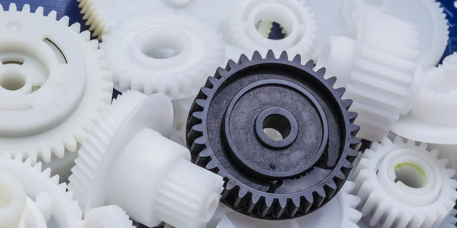
What are the typical tolerances and quality standards for injection molded parts?
When it comes to injection molded parts, the tolerances and quality standards can vary depending on several factors, including the specific application, industry requirements, and the capabilities of the injection molding process. Here are some general considerations regarding tolerances and quality standards:
Tolerances:
The tolerances for injection molded parts typically refer to the allowable deviation from the intended design dimensions. These tolerances are influenced by various factors, including the part geometry, material properties, mold design, and process capabilities. It’s important to note that achieving tighter tolerances often requires more precise tooling, tighter process control, and additional post-processing steps. Here are some common types of tolerances found in injection molding:
1. Dimensional Tolerances:
Dimensional tolerances define the acceptable range of variation for linear dimensions, such as length, width, height, and diameter. The specific tolerances depend on the part’s critical dimensions and functional requirements. Typical dimensional tolerances for injection molded parts can range from +/- 0.05 mm to +/- 0.5 mm or even tighter, depending on the complexity of the part and the process capabilities.
2. Geometric Tolerances:
Geometric tolerances specify the allowable variation in shape, form, and orientation of features on the part. These tolerances are often expressed using symbols and control the relationships between various geometric elements. Common geometric tolerances include flatness, straightness, circularity, concentricity, perpendicularity, and angularity. The specific geometric tolerances depend on the part’s design requirements and the manufacturing capabilities.
3. Surface Finish Tolerances:
Surface finish tolerances define the acceptable variation in the texture, roughness, and appearance of the part’s surfaces. The surface finish requirements are typically specified using roughness parameters, such as Ra (arithmetical average roughness) or Rz (maximum height of the roughness profile). The specific surface finish tolerances depend on the part’s aesthetic requirements, functional needs, and the material being used.
Quality Standards:
In addition to tolerances, injection molded parts are subject to various quality standards that ensure their performance, reliability, and consistency. These standards may be industry-specific or based on international standards organizations. Here are some commonly referenced quality standards for injection molded parts:
1. ISO 9001:
The ISO 9001 standard is a widely recognized quality management system that establishes criteria for the overall quality control and management of an organization. Injection molding companies often seek ISO 9001 certification to demonstrate their commitment to quality and adherence to standardized processes for design, production, and customer satisfaction.
2. ISO 13485:
ISO 13485 is a specific quality management system standard for medical devices. Injection molded parts used in the medical industry must adhere to this standard to ensure they meet the stringent quality requirements for safety, efficacy, and regulatory compliance.
3. Automotive Industry Standards:
The automotive industry has its own set of quality standards, such as ISO/TS 16949 (now IATF 16949), which focuses on the quality management system for automotive suppliers. These standards encompass requirements for product design, development, production, installation, and servicing, ensuring the quality and reliability of injection molded parts used in automobiles.
4. Industry-Specific Standards:
Various industries may have specific quality standards or guidelines that pertain to injection molded parts. For example, the aerospace industry may reference standards like AS9100, while the electronics industry may adhere to standards such as IPC-A-610 for acceptability of electronic assemblies.
It’s important to note that the specific tolerances and quality standards for injection molded parts can vary significantly depending on the application and industry requirements. Design engineers and manufacturers work together to define the appropriate tolerances and quality standards based on the functional requirements, cost considerations, and the capabilities of the injection molding process.
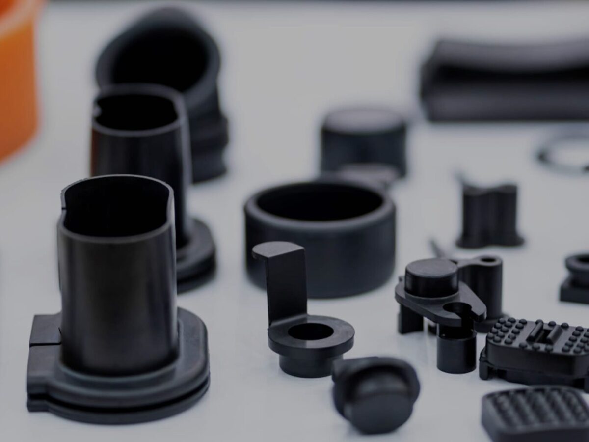
How do injection molded parts enhance the overall efficiency and functionality of products and equipment?
Injection molded parts play a crucial role in enhancing the overall efficiency and functionality of products and equipment. They offer numerous advantages that make them a preferred choice in various industries. Here’s a detailed explanation of how injection molded parts contribute to improved efficiency and functionality:
1. Design Flexibility:
Injection molding allows for intricate and complex part designs that can be customized to meet specific requirements. The flexibility in design enables the integration of multiple features, such as undercuts, threads, hinges, and snap fits, into a single molded part. This versatility enhances the functionality of the product or equipment by enabling the creation of parts that are precisely tailored to their intended purpose.
2. High Precision and Reproducibility:
Injection molding offers excellent dimensional accuracy and repeatability, ensuring consistent part quality throughout production. The use of precision molds and advanced molding techniques allows for the production of parts with tight tolerances and intricate geometries. This high precision and reproducibility enhance the efficiency of products and equipment by ensuring proper fit, alignment, and functionality of the molded parts.
3. Cost-Effective Mass Production:
Injection molding is a highly efficient and cost-effective method for mass production. Once the molds are created, the injection molding process can rapidly produce a large number of identical parts in a short cycle time. The ability to produce parts in high volumes streamlines the manufacturing process, reduces labor costs, and ensures consistent part quality. This cost-effectiveness contributes to overall efficiency and enables the production of affordable products and equipment.
4. Material Selection:
Injection molding offers a wide range of material options, including engineering thermoplastics, elastomers, and even certain metal alloys. The ability to choose from various materials with different properties allows manufacturers to select the most suitable material for each specific application. The right material selection enhances the functionality of the product or equipment by providing the desired mechanical, thermal, and chemical properties required for optimal performance.
5. Structural Integrity and Durability:
Injection molded parts are known for their excellent structural integrity and durability. The molding process ensures uniform material distribution, resulting in parts with consistent strength and reliability. The elimination of weak points, such as seams or joints, enhances the overall structural integrity of the product or equipment. Additionally, injection molded parts are resistant to impact, wear, and environmental factors, ensuring long-lasting functionality in demanding applications.
6. Integration of Features:
Injection molding enables the integration of multiple features into a single part. This eliminates the need for assembly or additional components, simplifying the manufacturing process and reducing production time and costs. The integration of features such as hinges, fasteners, or mounting points enhances the overall efficiency and functionality of the product or equipment by providing convenient and streamlined solutions.
7. Lightweight Design:
Injection molded parts can be manufactured with lightweight materials without compromising strength or durability. This is particularly advantageous in industries where weight reduction is critical, such as automotive, aerospace, and consumer electronics. The use of lightweight injection molded parts improves energy efficiency, reduces material costs, and enhances the overall performance and efficiency of the products and equipment.
8. Consistent Surface Finish:
Injection molding produces parts with a consistent and high-quality surface finish. The use of polished or textured molds ensures that the molded parts have smooth, aesthetic surfaces without the need for additional finishing operations. This consistent surface finish enhances the overall functionality and visual appeal of the product or equipment, contributing to a positive user experience.
9. Customization and Branding:
Injection molding allows for customization and branding options, such as incorporating logos, labels, or surface textures, directly into the molded parts. This customization enhances the functionality and marketability of products and equipment by providing a unique identity and reinforcing brand recognition.
Overall, injection molded parts offer numerous advantages that enhance the efficiency and functionality of products and equipment. Their design flexibility, precision, cost-effectiveness, material selection, structural integrity, lightweight design, and customization capabilities make them a preferred choice for a wide range of applications across industries.

What are injection molded parts, and how are they manufactured?
Injection molded parts are components or products that are produced through the injection molding manufacturing process. Injection molding is a widely used manufacturing technique for creating plastic parts with high precision, complexity, and efficiency. Here’s a detailed explanation of injection molded parts and the process of manufacturing them:
Injection Molding Process:
The injection molding process involves the following steps:
1. Mold Design:
The first step in manufacturing injection molded parts is designing the mold. The mold is a custom-made tool that defines the shape and features of the final part. It is typically made from steel or aluminum and consists of two halves: the cavity and the core. The mold design takes into account factors such as part geometry, material selection, cooling requirements, and ejection mechanism.
2. Material Selection:
The next step is selecting the appropriate material for the injection molding process. Thermoplastic polymers are commonly used due to their ability to melt and solidify repeatedly without significant degradation. The material choice depends on the desired properties of the final part, such as strength, flexibility, transparency, or chemical resistance.
3. Melting and Injection:
In the injection molding machine, the selected thermoplastic material is melted and brought to a molten state. The molten material, called the melt, is then injected into the mold under high pressure. The injection is performed through a nozzle and a runner system that delivers the molten material to the mold cavity.
4. Cooling:
After the molten material is injected into the mold, it begins to cool and solidify. Cooling is a critical phase of the injection molding process as it determines the final part’s dimensional accuracy, strength, and other properties. The mold is designed with cooling channels or inserts to facilitate the efficient and uniform cooling of the part. Cooling time can vary depending on factors such as part thickness, material properties, and mold design.
5. Mold Opening and Ejection:
Once the injected material has sufficiently cooled and solidified, the mold opens, separating the two halves. Ejector pins or other mechanisms are used to push or release the part from the mold cavity. The ejection system must be carefully designed to avoid damaging the part during the ejection process.
6. Finishing:
After ejection, the injection molded part may undergo additional finishing processes, such as trimming excess material, removing sprues or runners, and applying surface treatments or textures. These processes help achieve the desired final appearance and functionality of the part.
Advantages of Injection Molded Parts:
Injection molded parts offer several advantages:
1. High Precision and Complexity:
Injection molding allows for the creation of parts with high precision and intricate details. The molds can produce complex shapes, fine features, and precise dimensions, enabling the manufacturing of parts with tight tolerances.
2. Cost-Effective Mass Production:
Injection molding is a highly efficient process suitable for large-scale production. Once the mold is created, the manufacturing process can be automated, resulting in fast and cost-effective production of identical parts. The high production volumes help reduce per-unit costs.
3. Material Versatility:
Injection molding supports a wide range of thermoplastic materials, allowing for versatility in material selection based on the desired characteristics of the final part. Different materials can be used to achieve specific properties such as strength, flexibility, heat resistance, or chemical resistance.
4. Strength and Durability:
Injection molded parts can exhibit excellent strength and durability. The molding process ensures that the material is uniformly distributed, resulting in consistent mechanical properties throughout the part. This makes injection molded parts suitable for various applications that require structural integrity and longevity.
5. Minimal Post-Processing:
Injection molded parts often require minimal post-processing. The high precision and quality achieved during the molding process reduce the need for extensive additional machining or finishing operations, saving time and costs.
6. Design Flexibility:
With injection molding, designers have significant flexibility in part design. The process can accommodate complex geometries, undercuts, thin walls, and other design features that may be challenging or costly with other manufacturing methods. This flexibility allows for innovation and optimization of part functionality.
In summary, injection molded parts are components or products manufactured through the injection molding process. This process involves designing amold, selecting the appropriate material, melting and injecting the material into the mold, cooling and solidifying the part, opening the mold and ejecting the part, and applying finishing processes as necessary. Injection molded parts offer advantages such as high precision, complexity, cost-effective mass production, material versatility, strength and durability, minimal post-processing, and design flexibility. These factors contribute to the widespread use of injection molding in various industries for producing high-quality plastic parts.


editor by CX 2024-01-03
China manufacturer & factory supplier for china in Faisalabad Pakistan supplier factory exporter hydraulic motor with brake With high quality best price & service

factory of roller chains. Conveyor chains, engineered chains, silent chains, and tabletop chains are also available. Other energy transmission products consist of pillow blocks, conveyor idlers, conveyor pulleys, drive shafts, equipment racks, gear reducers, gears, overrunning clutches, motor bases, pulleys, screw conveyors, shaft couplings, sheaves, speed reducers, sprockets, tapered bushings, tensioners, torque limiters, and universal joints. Services this sort of as bearing reconditioning and repair, ball screw restore, custom contract machining, gearbox mend and overrunning clutch fix services are offered. Roller chains can be employed in conveyor and equipment manufacturing, industrial processing, equipment rebuilding, squander h2o, sand and gravel, instrument and die, metal, metals and scrap processing industrial programs.Innovative thermo remedy equipment, such as network warmth remedy oven, multi-use thermo therapy oven, etc.
Overview
Quick Information
- Following Warranty Support:
-
Video technical help
- Regional Service Location:
-
Egypt
- Showroom Place:
-
Egypt
- Type:
-
areas
- After-income Support Provided:
-
Movie specialized assist
Supply Ability
- Source Ability:
- 3000 Piece/Items for each Thirty day period
Packaging & Supply
- Packaging Details
- packaged in plywood scenario or PALLET
- Port
- NINGBO/SHANGHAI, CHINA
-
Guide Time
: -
Quantity(Bags) 1 – 20 >20 Est. Time(days) 15 To be negotiated
On the web Customization
| TYPE |
Displacement (ml/r) |
Stress (Mpa) |
Torque (N.M) |
Pace range |
Max Cont Power |
|||
|
SinglAdhering to “Survival by Good quality, Advancement by Technology & Credit”, The business will continually improve product efficiency to fulfill the escalating client specifications in the arduous style of perform. e Pace |
Double Speed |
Peak strain |
Cont Pressure |
Rate torque |
Theoric torque |
|||
| TMS08-630 | 627 | 314 | forty | twenty five | 2371 | ninety four | -170 | 36 |
| TMS08-seven hundred | 702 | 351 | 40 | twenty five | 2654 | 106 | -a hundred and seventy | 36 |
| TMS08-780 | Our PTO travel shafts enable the user straightforward upkeep. The greasing nipples on normal crosses are positioned beneath angle to allow the consumer much better accessibility. Easier entry is also attainable simply because of the versatile cone. We listened to the needs of our consumers and positioned the greasing nipple at extensive-angle PTO’s into the cross bearing. The other novelty, we introduced with extensive-angle PTO push shafts is in line greasing. We desired to moreover simplify the routine maintenance and extend the lifespan of joints.780 | 390 | 40 | twenty five | 2949 | 117 | -one hundred seventy | 36 |
| TMS08-860 | 857 | 429 | 40 | twenty five | 3241 | 129 | -a hundred and seventy | 36 |
| TMS08-930 | 934 | 467 | forty | twenty five | 3532 | 141 | -a hundred and seventy | 36 |
| TMS08-1050 | 1043 | 522 | 35 | twenty five | 3944 | 157 | -100 | 36 |
| TMS08-1150 | 1146 | 573 | 35 | 25 | 4333 | 173 | -a hundred | 36 |
| TMS08-1250 | 1248 | 624 | 35 | twenty five | 4719 | 188 | -90 | 36 |
| TYPE |
Displacement (ml/r) |
Force (Mpa) |
Torque (N.M) |
Speed range |
Max Cont Power |
|||
|
Solitary Speed |
Double Pace |
Peak force |
Cont Strain |
Charge torque |
Theoric torque |
|||
| TMS11-840 | 837 | 419 | 40 | twenty five | 3165 | 126 | -a hundred and fifty | forty four |
| TMS11-950 | 943 | 472 | 40 | twenty five | 3566 | 142 | -one hundred fifty | forty four |
| TMS11-1050 | 1048 | 524 | 40 | 25 | 3963 | 158 | -one hundred fifty | forty four |
| TMS11-1260 | 1259 | 630 | forty | 25 | 4761 | one hundred ninety | -a hundred and fifty | forty four |
| TMS11-1270 | 1263 | 632 | 35 | twenty five | 4776 | 191 | -150 | forty four |
| TMS11-1400 | 1404 | 702 | 35 | 25 | 5309 | 212 | -eighty | 44 |
| TMS11-1550 | 1536 | 768 | 35 | twenty five | 5808 | 232 | -80 | 44 |
| TMS11-1700 | 1687 | 844 | 35 | twenty five | 6379 | 255 | -eighty | 44 |
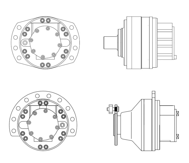

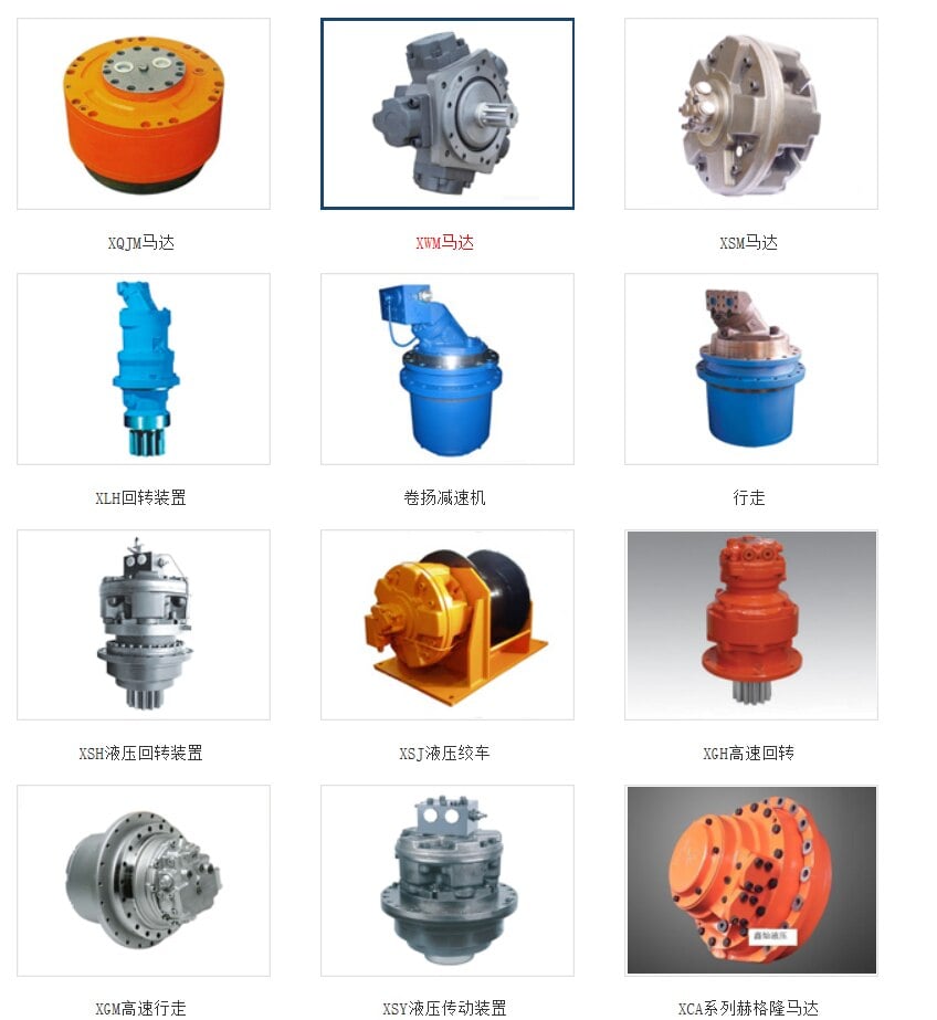




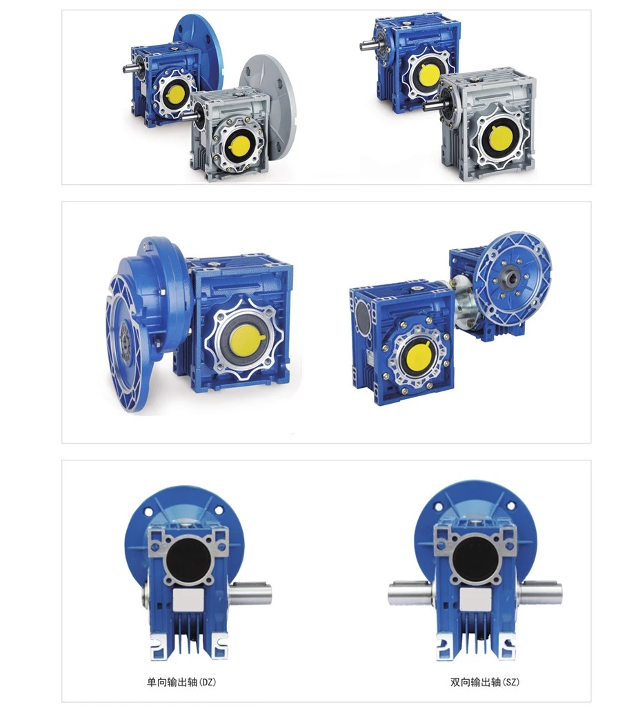
RV025~RV150 Strong Shaft Enter RV025~RV150 Functions: 1. High quality aluminum alloy gear box, mild bodyweight and not rust 2. 2 optional worm wheel resources: Tin (Stannum) bronze or aluminum bronze alloy 3. Normal components and quite versatile for shaft configurations and motor flange interface 4. Many optional mounting alternatives 5. Reduced noise, High effectiveness in heat dissipation


Best China manufacturer & factory china in Sukkur Pakistan supplier low speed high torque motorSwivelling Hydraulic motoremd hydraulic motor With high quality best price

Quality and credit are the bases that make a corporation alive. a specialized supplier Worm gears are the most compact type of system and provide high-ratio speed reduction. They are often the preferred type of gearing system when space is limited and large gear reductions are needed. Worm gears can be used to either greatly increase torque or greatly reduce speed. They are also the smoothest and quietest of the gear systems, as long as they are properly mounted and lubricated.of a full range of chains, sprockets, gears, gear racks, V-belts, couplings and reducers, pto shaft, agricultural gearboxes….
Overview
Quick Details
- EPG is specialized in design, manufacturer and sales of agricultural machinery and farm implements, which has an independent import and export rights. After Warranty Service:
-
Video technical support
We designed, especially for our customers, a protective cone which is flexible and enables easier handling while coupling the PTO on the tractor or working machine. The flexible cone offers additional comfort when coupling the PTO, because you can get a good grip in the limited shaft space.
- Local Service Location:
-
Egypt
- Showroom Location:
-
Egypt
- Type:
-
parts
- After-sales Service Provided:
-
Video technical support
Supply Ability
- Supply Ability:
- 3000 Piece/Pieces per Month
Packaging & Delivery
- Packaging Details
- packaged in plywood case or PALLET
- Port
- Ningbo
Online Customization
Cont pressure 25MPa emd hydraulic motor
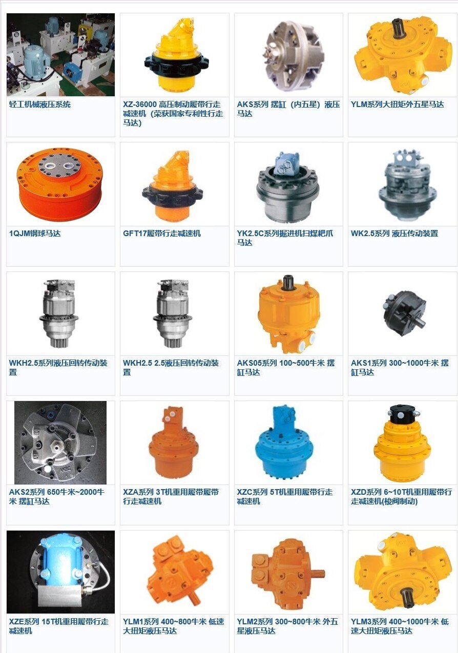
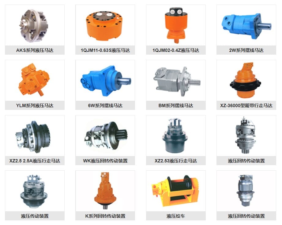
Product Description

![]()
Characteristics


Characteristics:
1.Low noise
2.High staring torque ( mechanical efficiency improved to over 0.9 ), good stability when low speed.
3.High volumetic efficiency
4.Higher mechanical efficiency
5.Opposite rotating available
6.Radial and axial load available
7.Higher kw/kg rati
TECHNICAL DATA


More Product


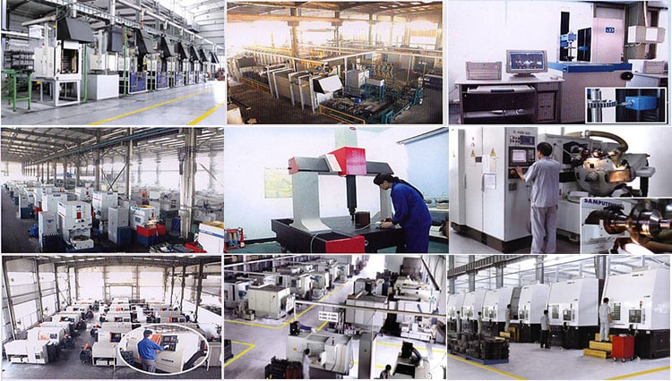
Company Information



Packaging & Shipping
| OEM | yes |
| Lead Time | 5-20 working days for less than 1500pcs |
| Payment | L/C,T/T |
| 30% advance payment,the balance paid before shipment | |
| Packing | Motor each have their own carton,the outer packing is a five-layer plywood boxes |
| Shipping | 1)By air or sea or combined transportation |
| 2)Express:TNT,FEDEX,UPS,DHL |

Our Services


Contact Us


