Product Description
Torque Limiter Couplings High Torque Shaft Coulings Torque Limiter For Plant Machinery
Description:
The ZTSC safety clutch can provide cost-effective protection and reliable operation while ensuring the highest utilization of machinery and equipment.
When the driving machinery of the device is overloaded or the transmitted torque exceeds the set sliding torque, the steel ball leaves the groove of the support flange, the clutch disengages, causing the active end component and the driven end component to slip. At this time, the transmitted torque decreases to a very small amount, and the transmitting ring generates axial displacement. The limit switch of the sensor is triggered to connect the sensor circuit and output a signal. Then, the output signal can be used to control the operation or cut off the power source, and the device stops rotating, playing a role in protecting the device. After the overload is eliminated, the steel ball rotates 360 ° in the cage rotation, and it will automatically close. In this way, the active end and driven end components will return to normal transmission in their original positions after rotating each other for 1 cycle.
Advantages:
1. Lowest price based on large scale production.
2. High and stable quality level.
3. Widely used in various mechanical and hydraulic fields.
4. Compensation for axial, radial and angular misalignment.
5. Convenient axial plugging assembly.
6. No brittlement at low temperature.
7. Good slippery and frictional properties.
8. Resistance to chemical corrosion.
9. Rich experience working with big companies in this field.
Product parameters:
Packing & shipping:
1 Prevent from damage.
2. As customers’ requirements, in perfect condition.
3. Delivery : As per contract delivery on time
4. Shipping : As per client request. We can accept CIF, Door to Door etc. or client authorized agent we supply all the necessary assistant.
FAQ:
Q 1: Are you a trading company or a manufacturer?
A: We are a professional manufacturer specializing in manufacturing various series of couplings.
Q 2:Can you do OEM?
Yes, we can. We can do OEM & ODM for all the customers with customized artworks in PDF or AI format.
Q 3:How long is your delivery time?
Generally, it is 20-30 days if the goods are not in stock. It is according to quantity.
Q 4: How long is your warranty?
A: Our Warranty is 12 months under normal circumstances.
Q 5: Do you have inspection procedures for coupling?
A:100% self-inspection before packing.
Q 6: Can I have a visit to your factory before the order?
A: Sure, welcome to visit our factory.
/* January 22, 2571 19:08:37 */!function(){function s(e,r){var a,o={};try{e&&e.split(“,”).forEach(function(e,t){e&&(a=e.match(/(.*?):(.*)$/))&&1
| Standard Or Nonstandard: | Standard |
|---|---|
| Shaft Hole: | 19-32 |
| Torque: | >80N.M |
| Bore Diameter: | 19mm |
| Speed: | 4000r/M |
| Structure: | Rigid |
| Customization: |
Available
|
|
|---|
Can you explain the role of temperature and pressure in injection molding quality control?
Temperature and pressure are two critical parameters in injection molding that significantly impact the quality control of the process. Let’s explore their roles in more detail:
Temperature:
The temperature in injection molding plays several important roles in ensuring quality control:
1. Material Flow and Fill:
The temperature of the molten plastic material affects its viscosity, or flowability. Higher temperatures reduce the material’s viscosity, allowing it to flow more easily into the mold cavities during the injection phase. Proper temperature control ensures optimal material flow and fill, preventing issues such as short shots, flow marks, or incomplete part filling. Temperature control also helps ensure consistent material properties and dimensional accuracy in the final parts.
2. Melting and Homogenization:
The temperature must be carefully controlled during the melting process to ensure complete melting and homogenization of the plastic material. Insufficient melting can result in unmelted particles or inconsistent material properties, leading to defects in the molded parts. Proper temperature control during the melting phase ensures uniform melting and mixing of additives, enhancing material homogeneity and the overall quality of the molded parts.
3. Cooling and Solidification:
After the molten plastic is injected into the mold, temperature control is crucial during the cooling and solidification phase. Proper cooling rates and uniform cooling help prevent issues such as warping, shrinkage, or part distortion. Controlling the temperature allows for consistent solidification throughout the part, ensuring dimensional stability and minimizing internal stresses. Temperature control also affects the part’s crystallinity and microstructure, which can impact its mechanical properties.
Pressure:
Pressure control is equally important in achieving quality control in injection molding:
1. Material Packing:
During the packing phase of injection molding, pressure is applied to the molten plastic material to compensate for shrinkage as it cools and solidifies. Proper pressure control ensures that the material is adequately packed into the mold cavities, minimizing voids, sinks, or part deformation. Insufficient packing pressure can lead to incomplete filling and poor part quality, while excessive pressure can cause excessive stress, part distortion, or flash.
2. Gate and Flow Control:
The pressure in injection molding influences the flow behavior of the material through the mold. The pressure at the gate, where the molten plastic enters the mold cavity, needs to be carefully controlled. The gate pressure affects the material’s flow rate, filling pattern, and packing efficiency. Optimal gate pressure ensures uniform flow and fill, preventing issues like flow lines, weld lines, or air traps that can compromise part quality.
3. Ejection and Part Release:
Pressure control is essential during the ejection phase to facilitate the easy removal of the molded part from the mold. Adequate ejection pressure helps overcome any adhesion or friction between the part and the mold surfaces, ensuring smooth and damage-free part release. Improper ejection pressure can result in part sticking, part deformation, or mold damage.
4. Process Monitoring and Feedback:
Monitoring and controlling the temperature and pressure parameters in real-time are crucial for quality control. Advanced injection molding machines are equipped with sensors and control systems that continuously monitor temperature and pressure. These systems provide feedback and allow for adjustments during the process to maintain optimum conditions and ensure consistent part quality.
Overall, temperature and pressure control in injection molding are vital for achieving quality control. Proper temperature control ensures optimal material flow, melting, homogenization, cooling, and solidification, while pressure control ensures proper material packing, gate and flow control, ejection, and part release. Monitoring and controlling these parameters throughout the injection molding process contribute to the production of high-quality parts with consistent dimensions, mechanical properties, and surface finish.
Can you provide guidance on the selection of injection molded materials based on application requirements?
Yes, I can provide guidance on the selection of injection molded materials based on application requirements. The choice of material for injection molding plays a critical role in determining the performance, durability, and functionality of the molded parts. Here’s a detailed explanation of the factors to consider and the guidance for selecting the appropriate material:
1. Mechanical Properties:
Consider the mechanical properties required for the application, such as strength, stiffness, impact resistance, and wear resistance. Different materials have varying mechanical characteristics, and selecting a material with suitable properties is crucial. For example, engineering thermoplastics like ABS, PC, or nylon offer high strength and impact resistance, while materials like PEEK or ULTEM provide exceptional mechanical performance at elevated temperatures.
2. Chemical Resistance:
If the part will be exposed to chemicals, consider the chemical resistance of the material. Some materials, like PVC or PTFE, exhibit excellent resistance to a wide range of chemicals, while others may be susceptible to degradation or swelling. Ensure that the selected material can withstand the specific chemicals it will encounter in the application environment.
3. Thermal Properties:
Evaluate the operating temperature range of the application and choose a material with suitable thermal properties. Materials like PPS, PEEK, or LCP offer excellent heat resistance, while others may have limited temperature capabilities. Consider factors such as the maximum temperature, thermal stability, coefficient of thermal expansion, and heat transfer requirements of the part.
4. Electrical Properties:
For electrical or electronic applications, consider the electrical properties of the material. Materials like PBT or PPS offer good electrical insulation properties, while others may have conductive or dissipative characteristics. Determine the required dielectric strength, electrical conductivity, surface resistivity, and other relevant electrical properties for the application.
5. Environmental Conditions:
Assess the environmental conditions the part will be exposed to, such as humidity, UV exposure, outdoor weathering, or extreme temperatures. Some materials, like ASA or HDPE, have excellent weatherability and UV resistance, while others may degrade or become brittle under harsh conditions. Choose a material that can withstand the specific environmental factors to ensure long-term performance and durability.
6. Regulatory Compliance:
Consider any regulatory requirements or industry standards that the material must meet. Certain applications, such as those in the medical or food industries, may require materials that are FDA-approved or comply with specific certifications. Ensure that the selected material meets the necessary regulatory and safety standards for the intended application.
7. Cost Considerations:
Evaluate the cost implications associated with the material selection. Different materials have varying costs, and the material choice should align with the project budget. Consider not only the material cost per unit but also factors like tooling expenses, production efficiency, and the overall lifecycle cost of the part.
8. Material Availability and Processing:
Check the availability of the material and consider its processability in injection molding. Ensure that the material is readily available from suppliers and suitable for the specific injection molding process parameters, such as melt flow rate, moldability, and compatibility with the chosen molding equipment.
9. Material Testing and Validation:
Perform material testing and validation to ensure that the selected material meets the required specifications and performance criteria. Conduct mechanical, thermal, chemical, and electrical tests to verify the material’s properties and behavior under application-specific conditions.
Consider consulting with material suppliers, engineers, or experts in injection molding to get further guidance and recommendations based on the specific application requirements. They can provide valuable insights into material selection based on their expertise and knowledge of industry standards and best practices.
By carefully considering these factors and guidance, you can select the most appropriate material for injection molding that meets the specific application requirements, ensuring optimal performance, durability, and functionality of the molded parts.
What are injection molded parts, and how are they manufactured?
Injection molded parts are components or products that are produced through the injection molding manufacturing process. Injection molding is a widely used manufacturing technique for creating plastic parts with high precision, complexity, and efficiency. Here’s a detailed explanation of injection molded parts and the process of manufacturing them:
Injection Molding Process:
The injection molding process involves the following steps:
1. Mold Design:
The first step in manufacturing injection molded parts is designing the mold. The mold is a custom-made tool that defines the shape and features of the final part. It is typically made from steel or aluminum and consists of two halves: the cavity and the core. The mold design takes into account factors such as part geometry, material selection, cooling requirements, and ejection mechanism.
2. Material Selection:
The next step is selecting the appropriate material for the injection molding process. Thermoplastic polymers are commonly used due to their ability to melt and solidify repeatedly without significant degradation. The material choice depends on the desired properties of the final part, such as strength, flexibility, transparency, or chemical resistance.
3. Melting and Injection:
In the injection molding machine, the selected thermoplastic material is melted and brought to a molten state. The molten material, called the melt, is then injected into the mold under high pressure. The injection is performed through a nozzle and a runner system that delivers the molten material to the mold cavity.
4. Cooling:
After the molten material is injected into the mold, it begins to cool and solidify. Cooling is a critical phase of the injection molding process as it determines the final part’s dimensional accuracy, strength, and other properties. The mold is designed with cooling channels or inserts to facilitate the efficient and uniform cooling of the part. Cooling time can vary depending on factors such as part thickness, material properties, and mold design.
5. Mold Opening and Ejection:
Once the injected material has sufficiently cooled and solidified, the mold opens, separating the two halves. Ejector pins or other mechanisms are used to push or release the part from the mold cavity. The ejection system must be carefully designed to avoid damaging the part during the ejection process.
6. Finishing:
After ejection, the injection molded part may undergo additional finishing processes, such as trimming excess material, removing sprues or runners, and applying surface treatments or textures. These processes help achieve the desired final appearance and functionality of the part.
Advantages of Injection Molded Parts:
Injection molded parts offer several advantages:
1. High Precision and Complexity:
Injection molding allows for the creation of parts with high precision and intricate details. The molds can produce complex shapes, fine features, and precise dimensions, enabling the manufacturing of parts with tight tolerances.
2. Cost-Effective Mass Production:
Injection molding is a highly efficient process suitable for large-scale production. Once the mold is created, the manufacturing process can be automated, resulting in fast and cost-effective production of identical parts. The high production volumes help reduce per-unit costs.
3. Material Versatility:
Injection molding supports a wide range of thermoplastic materials, allowing for versatility in material selection based on the desired characteristics of the final part. Different materials can be used to achieve specific properties such as strength, flexibility, heat resistance, or chemical resistance.
4. Strength and Durability:
Injection molded parts can exhibit excellent strength and durability. The molding process ensures that the material is uniformly distributed, resulting in consistent mechanical properties throughout the part. This makes injection molded parts suitable for various applications that require structural integrity and longevity.
5. Minimal Post-Processing:
Injection molded parts often require minimal post-processing. The high precision and quality achieved during the molding process reduce the need for extensive additional machining or finishing operations, saving time and costs.
6. Design Flexibility:
With injection molding, designers have significant flexibility in part design. The process can accommodate complex geometries, undercuts, thin walls, and other design features that may be challenging or costly with other manufacturing methods. This flexibility allows for innovation and optimization of part functionality.
In summary, injection molded parts are components or products manufactured through the injection molding process. This process involves designing amold, selecting the appropriate material, melting and injecting the material into the mold, cooling and solidifying the part, opening the mold and ejecting the part, and applying finishing processes as necessary. Injection molded parts offer advantages such as high precision, complexity, cost-effective mass production, material versatility, strength and durability, minimal post-processing, and design flexibility. These factors contribute to the widespread use of injection molding in various industries for producing high-quality plastic parts.


editor by CX 2024-03-18
China Good quality Highly Demanded Agricultural Machinery Tractor Drive Shaft Ratchet Torque Limiter
Product Description
Product Description
A ratchet torque limiter is a device able to interrupt the transmission of power in the event of a orque CHINAMFG or overload that exceeds the setting. The torque limiter is automatically re-engaged after the cause of the overload is removed. Ratchet torque limiters are generally employed to protect t implements subjected to constant or alternating torque from overloads.
The setting is normally 2 to 3 times the median torque M.
When the device is slipping, the user should promptly stop the PTO to avoid excessive wear.
Ratchet torque limiters should be used only on drivelines operating at speeds less than 700 RPM.
Here is our advantages when compare to similar products from China:
1.Forged yokes make PTO shafts strong enough for usage and working;
2.Internal sizes standard to confirm installation smooth;
3.CE and ISO certificates to guarantee to quality of our goods;
4.Strong and professional package to confirm the good situation when you receive the goods.
Product Specifications
Packaging & Shipping
Certifications
Company Profile
HangZhou Hanon Technology Co.,ltd is a modern enterprise specilizing in the development,production,sales and services of Agricultural Parts like PTO shaft and Gearboxes and Hydraulic parts like Cylinder , Valve ,Gearpump and motor etc..
We adhere to the principle of ” High Quality, Customers’Satisfaction”, using advanced technology and equipments to ensure all the technical standards of transmission .We follow the principle of people first , trying our best to set up a pleasant surroundings and platform of performance for each employee. So everyone can be self-consciously active to join Hanon Machinery.
FAQ
1.WHAT’S THE PAYMENT TERM?
When we quote for you,we will confirm with you the way of transaction,FOB,CIFetc.<br> For mass production goods, you need to pay 30% deposit before producing and70% balance against copy of documents.The most common way is by T/T.
2.HOW TO DELIVER THE GOODS TO US?
Usually we will ship the goods to you by sea.
3.How long is your delivery time and shipment?
30-45days
/* March 10, 2571 17:59:20 */!function(){function s(e,r){var a,o={};try{e&&e.split(“,”).forEach(function(e,t){e&&(a=e.match(/(.*?):(.*)$/))&&1
| Type: | Ratchet Torque Limiter |
|---|---|
| Usage: | Pto Shaft |
| Material: | 45cr Steel |
| Power Source: | Pto Shaft |
| Weight: | 1-2kg |
| After-sales Service: | Online Support |
| Samples: |
US$ 20/Piece
1 Piece(Min.Order) | |
|---|
| Customization: |
Available
|
|
|---|
How does the injection molding process contribute to the production of high-precision parts?
The injection molding process is widely recognized for its ability to produce high-precision parts with consistent quality. Several factors contribute to the precision achieved through injection molding:
1. Tooling and Mold Design:
The design and construction of the injection mold play a crucial role in achieving high precision. The mold is typically made with precision machining techniques, ensuring accurate dimensions and tight tolerances. The mold design considers factors such as part shrinkage, cooling channels, gate location, and ejection mechanisms, all of which contribute to dimensional accuracy and part stability during the molding process.
2. Material Control:
Injection molding allows for precise control over the material used in the process. The molten plastic material is carefully measured and controlled, ensuring consistent material properties and reducing variations in the molded parts. This control over material parameters, such as melt temperature, viscosity, and fill rate, contributes to the production of high-precision parts with consistent dimensions and mechanical properties.
3. Injection Process Control:
The injection molding process involves injecting molten plastic into the mold cavity under high pressure. Advanced injection molding machines are equipped with precise control systems that regulate the injection speed, pressure, and time. These control systems ensure accurate and repeatable filling of the mold, minimizing variations in part dimensions and surface finish. The ability to finely tune and control these parameters contributes to the production of high-precision parts.
4. Cooling and Solidification:
Proper cooling and solidification of the injected plastic material are critical for achieving high precision. The cooling process is carefully controlled to ensure uniform cooling throughout the part and to minimize warping or distortion. Efficient cooling systems in the mold, such as cooling channels or conformal cooling, help maintain consistent temperatures and solidification rates, resulting in precise part dimensions and reduced internal stresses.
5. Automation and Robotics:
The use of automation and robotics in injection molding enhances precision and repeatability. Automated systems ensure consistent and precise handling of molds, inserts, and finished parts, reducing human errors and variations. Robots can perform tasks such as part removal, inspection, and assembly with high accuracy, contributing to the overall precision of the production process.
6. Process Monitoring and Quality Control:
Injection molding processes often incorporate advanced monitoring and quality control systems. These systems continuously monitor and analyze key process parameters, such as temperature, pressure, and cycle time, to detect any variations or deviations. Real-time feedback from these systems allows for adjustments and corrective actions, ensuring that the production remains within the desired tolerances and quality standards.
7. Post-Processing and Finishing:
After the injection molding process, post-processing and finishing techniques, such as trimming, deburring, and surface treatments, can further enhance the precision and aesthetics of the parts. These processes help remove any imperfections or excess material, ensuring that the final parts meet the specified dimensional and cosmetic requirements.
Collectively, the combination of precise tooling and mold design, material control, injection process control, cooling and solidification techniques, automation and robotics, process monitoring, and post-processing contribute to the production of high-precision parts through the injection molding process. The ability to consistently achieve tight tolerances, accurate dimensions, and excellent surface finish makes injection molding a preferred choice for applications that demand high precision.
What eco-friendly or sustainable practices are associated with injection molding processes and materials?
Eco-friendly and sustainable practices are increasingly important in the field of injection molding. Many advancements have been made to minimize the environmental impact of both the processes and materials used in injection molding. Here’s a detailed explanation of the eco-friendly and sustainable practices associated with injection molding processes and materials:
1. Material Selection:
The choice of materials can significantly impact the environmental footprint of injection molding. Selecting eco-friendly materials is a crucial practice. Some sustainable material options include biodegradable or compostable polymers, such as PLA or PHA, which can reduce the environmental impact of the end product. Additionally, using recycled or bio-based materials instead of virgin plastics can help to conserve resources and reduce waste.
2. Recycling:
Implementing recycling practices is an essential aspect of sustainable injection molding. Recycling involves collecting, processing, and reusing plastic waste generated during the injection molding process. Both post-industrial and post-consumer plastic waste can be recycled and incorporated into new products, reducing the demand for virgin materials and minimizing landfill waste.
3. Energy Efficiency:
Efficient energy usage is a key factor in sustainable injection molding. Optimizing the energy consumption of machines, heating and cooling systems, and auxiliary equipment can significantly reduce the carbon footprint of the manufacturing process. Employing energy-efficient technologies, such as servo-driven machines or advanced heating and cooling systems, can help achieve energy savings and lower environmental impact.
4. Process Optimization:
Process optimization is another sustainable practice in injection molding. By fine-tuning process parameters, optimizing cycle times, and reducing material waste, manufacturers can minimize resource consumption and improve overall process efficiency. Advanced process control systems, real-time monitoring, and automation technologies can assist in achieving these optimization goals.
5. Waste Reduction:
Efforts to reduce waste are integral to sustainable injection molding practices. Minimizing material waste through improved design, better material handling techniques, and efficient mold design can positively impact the environment. Furthermore, implementing lean manufacturing principles and adopting waste management strategies, such as regrinding scrap materials or reusing purging compounds, can contribute to waste reduction and resource conservation.
6. Clean Production:
Adopting clean production practices helps mitigate the environmental impact of injection molding. This includes reducing emissions, controlling air and water pollution, and implementing effective waste management systems. Employing pollution control technologies, such as filters and treatment systems, can help ensure that the manufacturing process operates in an environmentally responsible manner.
7. Life Cycle Assessment:
Conducting a life cycle assessment (LCA) of the injection molded products can provide insights into their overall environmental impact. LCA evaluates the environmental impact of a product throughout its entire life cycle, from raw material extraction to disposal. By considering factors such as material sourcing, production, use, and end-of-life options, manufacturers can identify areas for improvement and make informed decisions to reduce the environmental footprint of their products.
8. Collaboration and Certification:
Collaboration among stakeholders, including manufacturers, suppliers, and customers, is crucial for fostering sustainable practices in injection molding. Sharing knowledge, best practices, and sustainability initiatives can drive eco-friendly innovations. Additionally, obtaining certifications such as ISO 14001 (Environmental Management System) or partnering with organizations that promote sustainable manufacturing can demonstrate a commitment to environmental responsibility and sustainability.
9. Product Design for Sustainability:
Designing products with sustainability in mind is an important aspect of eco-friendly injection molding practices. By considering factors such as material selection, recyclability, energy efficiency, and end-of-life options during the design phase, manufacturers can create products that are environmentally responsible and promote a circular economy.
Implementing these eco-friendly and sustainable practices in injection molding processes and materials can help reduce the environmental impact of manufacturing, conserve resources, minimize waste, and contribute to a more sustainable future.
How do injection molded parts compare to other manufacturing methods in terms of cost and efficiency?
Injection molded parts have distinct advantages over other manufacturing methods when it comes to cost and efficiency. The injection molding process offers high efficiency and cost-effectiveness, especially for large-scale production. Here’s a detailed explanation of how injection molded parts compare to other manufacturing methods:
Cost Comparison:
Injection molding can be cost-effective compared to other manufacturing methods for several reasons:
1. Tooling Costs:
Injection molding requires an initial investment in creating molds, which can be costly. However, once the molds are made, they can be used repeatedly for producing a large number of parts, resulting in a lower per-unit cost. The amortized tooling costs make injection molding more cost-effective for high-volume production runs.
2. Material Efficiency:
Injection molding is highly efficient in terms of material usage. The process allows for precise control over the amount of material injected into the mold, minimizing waste. Additionally, excess material from the molding process can be recycled and reused, further reducing material costs compared to methods that generate more significant amounts of waste.
3. Labor Costs:
Injection molding is a highly automated process, requiring minimal labor compared to other manufacturing methods. Once the molds are set up and the process parameters are established, the injection molding machine can run continuously, producing parts with minimal human intervention. This automation reduces labor costs and increases overall efficiency.
Efficiency Comparison:
Injection molded parts offer several advantages in terms of efficiency:
1. Rapid Production Cycle:
Injection molding is a fast manufacturing process, capable of producing parts in a relatively short cycle time. The cycle time depends on factors such as part complexity, material properties, and cooling time. However, compared to other methods such as machining or casting, injection molding can produce multiple parts simultaneously in each cycle, resulting in higher production rates and improved efficiency.
2. High Precision and Consistency:
Injection molding enables the production of parts with high precision and consistency. The molds used in injection molding are designed to provide accurate and repeatable dimensional control. This precision ensures that each part meets the required specifications, reducing the need for additional machining or post-processing operations. The ability to consistently produce precise parts enhances efficiency and reduces time and costs associated with rework or rejected parts.
3. Scalability:
Injection molding is highly scalable, making it suitable for both low-volume and high-volume production. Once the molds are created, the injection molding process can be easily replicated, allowing for efficient production of identical parts. The ability to scale production quickly and efficiently makes injection molding a preferred method for meeting changing market demands.
4. Design Complexity:
Injection molding supports the production of parts with complex geometries and intricate details. The molds can be designed to accommodate undercuts, thin walls, and complex shapes that may be challenging or costly with other manufacturing methods. This flexibility in design allows for the integration of multiple components into a single part, reducing assembly requirements and potential points of failure. The ability to produce complex designs efficiently enhances overall efficiency and functionality.
5. Material Versatility:
Injection molding supports a wide range of thermoplastic materials, providing versatility in material selection based on the desired properties of the final part. Different materials can be chosen to achieve specific characteristics such as strength, flexibility, heat resistance, chemical resistance, or transparency. This material versatility allows for efficient customization and optimization of part performance.
In summary, injection molded parts are cost-effective and efficient compared to many other manufacturing methods. The initial tooling costs are offset by the ability to produce a large number of parts at a lower per-unit cost. The material efficiency, labor automation, rapid production cycle, high precision, scalability, design complexity, and material versatility contribute to the overall cost-effectiveness and efficiency of injection molding. These advantages make injection molding a preferred choice for various industries seeking to produce high-quality parts efficiently and economically.
editor by CX 2024-02-22
China Professional Agriculture Machinery Tractor Forged Clamp Bolt Pto Friction Torque Limiter with 2 Discs or 4 Discs Clamp Bolt
Product Description
FFV3-FFV4 Series Agricultural Riction Clamp Bolt PTO shaft Friction Torque Limiter with 2 Discs or 4 Discs for farm machinery
The torque limiter is activated when the setting torque exceeds the calibration torque. During the torque CHINAMFG limiting phase,the clutch continues to transmit power. The clutch is useful as a safety device tp protect against load peaks and to start machines with high rotational inertia. It is recommended to ensure that the setting value is correct to avoid excessive heating of the friction discs (insufficient setting) or clutch seizing (excessive seting).
Related products
Company Information
/* March 10, 2571 17:59:20 */!function(){function s(e,r){var a,o={};try{e&&e.split(“,”).forEach(function(e,t){e&&(a=e.match(/(.*?):(.*)$/))&&1
| Standard Or Nonstandard: | Standard |
|---|---|
| Shaft Hole: | 8-24 |
| Torque: | >80N.M |
| Bore Diameter: | OEM |
| Speed: | 4000r/M |
| Structure: | Flexible |
| Samples: |
US$ 9999/Piece
1 Piece(Min.Order) | |
|---|
What is the impact of material selection on the performance and durability of injection molded parts?
The material selection for injection molded parts has a significant impact on their performance and durability. The choice of material influences various key factors, including mechanical properties, chemical resistance, thermal stability, dimensional stability, and overall part functionality. Here’s a detailed explanation of the impact of material selection on the performance and durability of injection molded parts:
Mechanical Properties:
The mechanical properties of the material directly affect the part’s strength, stiffness, impact resistance, and fatigue life. Different materials exhibit varying levels of tensile strength, flexural strength, modulus of elasticity, and elongation at break. The selection of a material with appropriate mechanical properties ensures that the injection molded part can withstand the applied forces, vibrations, and operational stresses without failure or deformation.
Chemical Resistance:
The material’s resistance to chemicals and solvents is crucial in applications where the part comes into contact with aggressive substances. Certain materials, such as engineering thermoplastics like ABS (Acrylonitrile Butadiene Styrene) or PEEK (Polyether Ether Ketone), exhibit excellent chemical resistance. Choosing a material with the appropriate chemical resistance ensures that the injection molded part maintains its integrity and functionality when exposed to specific chemicals or environments.
Thermal Stability:
The thermal stability of the material is essential in applications that involve exposure to high temperatures or thermal cycling. Different materials have varying melting points, glass transition temperatures, and heat deflection temperatures. Selecting a material with suitable thermal stability ensures that the injection molded part can withstand the anticipated temperature variations without dimensional changes, warping, or degradation of mechanical properties.
Dimensional Stability:
The dimensional stability of the material is critical in applications where precise tolerances and dimensional accuracy are required. Some materials, such as engineering thermoplastics or filled polymers, exhibit lower coefficients of thermal expansion, minimizing the part’s dimensional changes with temperature variations. Choosing a material with good dimensional stability helps ensure that the injection molded part maintains its shape, size, and critical dimensions over a wide range of operating temperatures.
Part Functionality:
The material selection directly impacts the functionality and performance of the injection molded part. Different materials offer unique properties that can be tailored to meet specific application requirements. For example, materials like polycarbonate (PC) or polypropylene (PP) offer excellent transparency, making them suitable for applications requiring optical clarity, while materials like polyamide (PA) or polyoxymethylene (POM) provide low friction and wear resistance, making them suitable for moving or sliding parts.
Cycle Time and Processability:
The material selection can also affect the cycle time and processability of injection molding. Different materials have different melt viscosities and flow characteristics, which influence the filling and cooling times during the molding process. Materials with good flow properties can fill complex mold geometries more easily, reducing the cycle time and improving productivity. It’s important to select a material that can be effectively processed using the available injection molding equipment and techniques.
Cost Considerations:
The material selection also impacts the overall cost of the injection molded part. Different materials have varying costs, and selecting the most suitable material involves considering factors such as material availability, tooling requirements, processing conditions, and the desired performance characteristics. Balancing the performance requirements with cost considerations is crucial in achieving an optimal material selection that meets the performance and durability requirements within the budget constraints.
Overall, material selection plays a critical role in determining the performance, durability, and functionality of injection molded parts. Careful consideration of mechanical properties, chemical resistance, thermal stability, dimensional stability, part functionality, cycle time, processability, and cost factors helps ensure that the chosen material meets the specific application requirements and delivers the desired performance and durability over the part’s intended service life.
What eco-friendly or sustainable practices are associated with injection molding processes and materials?
Eco-friendly and sustainable practices are increasingly important in the field of injection molding. Many advancements have been made to minimize the environmental impact of both the processes and materials used in injection molding. Here’s a detailed explanation of the eco-friendly and sustainable practices associated with injection molding processes and materials:
1. Material Selection:
The choice of materials can significantly impact the environmental footprint of injection molding. Selecting eco-friendly materials is a crucial practice. Some sustainable material options include biodegradable or compostable polymers, such as PLA or PHA, which can reduce the environmental impact of the end product. Additionally, using recycled or bio-based materials instead of virgin plastics can help to conserve resources and reduce waste.
2. Recycling:
Implementing recycling practices is an essential aspect of sustainable injection molding. Recycling involves collecting, processing, and reusing plastic waste generated during the injection molding process. Both post-industrial and post-consumer plastic waste can be recycled and incorporated into new products, reducing the demand for virgin materials and minimizing landfill waste.
3. Energy Efficiency:
Efficient energy usage is a key factor in sustainable injection molding. Optimizing the energy consumption of machines, heating and cooling systems, and auxiliary equipment can significantly reduce the carbon footprint of the manufacturing process. Employing energy-efficient technologies, such as servo-driven machines or advanced heating and cooling systems, can help achieve energy savings and lower environmental impact.
4. Process Optimization:
Process optimization is another sustainable practice in injection molding. By fine-tuning process parameters, optimizing cycle times, and reducing material waste, manufacturers can minimize resource consumption and improve overall process efficiency. Advanced process control systems, real-time monitoring, and automation technologies can assist in achieving these optimization goals.
5. Waste Reduction:
Efforts to reduce waste are integral to sustainable injection molding practices. Minimizing material waste through improved design, better material handling techniques, and efficient mold design can positively impact the environment. Furthermore, implementing lean manufacturing principles and adopting waste management strategies, such as regrinding scrap materials or reusing purging compounds, can contribute to waste reduction and resource conservation.
6. Clean Production:
Adopting clean production practices helps mitigate the environmental impact of injection molding. This includes reducing emissions, controlling air and water pollution, and implementing effective waste management systems. Employing pollution control technologies, such as filters and treatment systems, can help ensure that the manufacturing process operates in an environmentally responsible manner.
7. Life Cycle Assessment:
Conducting a life cycle assessment (LCA) of the injection molded products can provide insights into their overall environmental impact. LCA evaluates the environmental impact of a product throughout its entire life cycle, from raw material extraction to disposal. By considering factors such as material sourcing, production, use, and end-of-life options, manufacturers can identify areas for improvement and make informed decisions to reduce the environmental footprint of their products.
8. Collaboration and Certification:
Collaboration among stakeholders, including manufacturers, suppliers, and customers, is crucial for fostering sustainable practices in injection molding. Sharing knowledge, best practices, and sustainability initiatives can drive eco-friendly innovations. Additionally, obtaining certifications such as ISO 14001 (Environmental Management System) or partnering with organizations that promote sustainable manufacturing can demonstrate a commitment to environmental responsibility and sustainability.
9. Product Design for Sustainability:
Designing products with sustainability in mind is an important aspect of eco-friendly injection molding practices. By considering factors such as material selection, recyclability, energy efficiency, and end-of-life options during the design phase, manufacturers can create products that are environmentally responsible and promote a circular economy.
Implementing these eco-friendly and sustainable practices in injection molding processes and materials can help reduce the environmental impact of manufacturing, conserve resources, minimize waste, and contribute to a more sustainable future.
How do injection molded parts compare to other manufacturing methods in terms of cost and efficiency?
Injection molded parts have distinct advantages over other manufacturing methods when it comes to cost and efficiency. The injection molding process offers high efficiency and cost-effectiveness, especially for large-scale production. Here’s a detailed explanation of how injection molded parts compare to other manufacturing methods:
Cost Comparison:
Injection molding can be cost-effective compared to other manufacturing methods for several reasons:
1. Tooling Costs:
Injection molding requires an initial investment in creating molds, which can be costly. However, once the molds are made, they can be used repeatedly for producing a large number of parts, resulting in a lower per-unit cost. The amortized tooling costs make injection molding more cost-effective for high-volume production runs.
2. Material Efficiency:
Injection molding is highly efficient in terms of material usage. The process allows for precise control over the amount of material injected into the mold, minimizing waste. Additionally, excess material from the molding process can be recycled and reused, further reducing material costs compared to methods that generate more significant amounts of waste.
3. Labor Costs:
Injection molding is a highly automated process, requiring minimal labor compared to other manufacturing methods. Once the molds are set up and the process parameters are established, the injection molding machine can run continuously, producing parts with minimal human intervention. This automation reduces labor costs and increases overall efficiency.
Efficiency Comparison:
Injection molded parts offer several advantages in terms of efficiency:
1. Rapid Production Cycle:
Injection molding is a fast manufacturing process, capable of producing parts in a relatively short cycle time. The cycle time depends on factors such as part complexity, material properties, and cooling time. However, compared to other methods such as machining or casting, injection molding can produce multiple parts simultaneously in each cycle, resulting in higher production rates and improved efficiency.
2. High Precision and Consistency:
Injection molding enables the production of parts with high precision and consistency. The molds used in injection molding are designed to provide accurate and repeatable dimensional control. This precision ensures that each part meets the required specifications, reducing the need for additional machining or post-processing operations. The ability to consistently produce precise parts enhances efficiency and reduces time and costs associated with rework or rejected parts.
3. Scalability:
Injection molding is highly scalable, making it suitable for both low-volume and high-volume production. Once the molds are created, the injection molding process can be easily replicated, allowing for efficient production of identical parts. The ability to scale production quickly and efficiently makes injection molding a preferred method for meeting changing market demands.
4. Design Complexity:
Injection molding supports the production of parts with complex geometries and intricate details. The molds can be designed to accommodate undercuts, thin walls, and complex shapes that may be challenging or costly with other manufacturing methods. This flexibility in design allows for the integration of multiple components into a single part, reducing assembly requirements and potential points of failure. The ability to produce complex designs efficiently enhances overall efficiency and functionality.
5. Material Versatility:
Injection molding supports a wide range of thermoplastic materials, providing versatility in material selection based on the desired properties of the final part. Different materials can be chosen to achieve specific characteristics such as strength, flexibility, heat resistance, chemical resistance, or transparency. This material versatility allows for efficient customization and optimization of part performance.
In summary, injection molded parts are cost-effective and efficient compared to many other manufacturing methods. The initial tooling costs are offset by the ability to produce a large number of parts at a lower per-unit cost. The material efficiency, labor automation, rapid production cycle, high precision, scalability, design complexity, and material versatility contribute to the overall cost-effectiveness and efficiency of injection molding. These advantages make injection molding a preferred choice for various industries seeking to produce high-quality parts efficiently and economically.
editor by CX 2024-01-30
China best Bestseller Iron Agricultural Machinery Tractor Drive Shaft Ratchet Torque Limiter
Product Description
Product Description
A ratchet torque limiter is a device able to interrupt the transmission of power in the event of a orque CHINAMFG or overload that exceeds the setting. The torque limiter is automatically re-engaged after the cause of the overload is removed. Ratchet torque limiters are generally employed to protect t implements subjected to constant or alternating torque from overloads.
The setting is normally 2 to 3 times the median torque M.
When the device is slipping, the user should promptly stop the PTO to avoid excessive wear.
Ratchet torque limiters should be used only on drivelines operating at speeds less than 700 RPM.
Here is our advantages when compare to similar products from China:
1.Forged yokes make PTO shafts strong enough for usage and working;
2.Internal sizes standard to confirm installation smooth;
3.CE and ISO certificates to guarantee to quality of our goods;
4.Strong and professional package to confirm the good situation when you receive the goods.
Product Specifications
Packaging & Shipping
Certifications
Company Profile
HangZhou Hanon Technology Co.,ltd is a modern enterprise specilizing in the development,production,sales and services of Agricultural Parts like PTO shaft and Gearboxes and Hydraulic parts like Cylinder , Valve ,Gearpump and motor etc..
We adhere to the principle of ” High Quality, Customers’Satisfaction”, using advanced technology and equipments to ensure all the technical standards of transmission .We follow the principle of people first , trying our best to set up a pleasant surroundings and platform of performance for each employee. So everyone can be self-consciously active to join Hanon Machinery.
FAQ
1.WHAT’S THE PAYMENT TERM?
When we quote for you,we will confirm with you the way of transaction,FOB,CIFetc.<br> For mass production goods, you need to pay 30% deposit before producing and70% balance against copy of documents.The most common way is by T/T.
2.HOW TO DELIVER THE GOODS TO US?
Usually we will ship the goods to you by sea.
3.How long is your delivery time and shipment?
30-45days
/* March 10, 2571 17:59:20 */!function(){function s(e,r){var a,o={};try{e&&e.split(“,”).forEach(function(e,t){e&&(a=e.match(/(.*?):(.*)$/))&&1
| Type: | Ratchet Torque Limiter |
|---|---|
| Usage: | Pto Shaft |
| Material: | 45cr Steel |
| Power Source: | Pto Shaft |
| Weight: | 1-2kg |
| After-sales Service: | Online Support |
| Samples: |
US$ 20/Piece
1 Piece(Min.Order) | |
|---|
| Customization: |
Available
|
|
|---|
What are the typical tolerances and quality standards for injection molded parts?
When it comes to injection molded parts, the tolerances and quality standards can vary depending on several factors, including the specific application, industry requirements, and the capabilities of the injection molding process. Here are some general considerations regarding tolerances and quality standards:
Tolerances:
The tolerances for injection molded parts typically refer to the allowable deviation from the intended design dimensions. These tolerances are influenced by various factors, including the part geometry, material properties, mold design, and process capabilities. It’s important to note that achieving tighter tolerances often requires more precise tooling, tighter process control, and additional post-processing steps. Here are some common types of tolerances found in injection molding:
1. Dimensional Tolerances:
Dimensional tolerances define the acceptable range of variation for linear dimensions, such as length, width, height, and diameter. The specific tolerances depend on the part’s critical dimensions and functional requirements. Typical dimensional tolerances for injection molded parts can range from +/- 0.05 mm to +/- 0.5 mm or even tighter, depending on the complexity of the part and the process capabilities.
2. Geometric Tolerances:
Geometric tolerances specify the allowable variation in shape, form, and orientation of features on the part. These tolerances are often expressed using symbols and control the relationships between various geometric elements. Common geometric tolerances include flatness, straightness, circularity, concentricity, perpendicularity, and angularity. The specific geometric tolerances depend on the part’s design requirements and the manufacturing capabilities.
3. Surface Finish Tolerances:
Surface finish tolerances define the acceptable variation in the texture, roughness, and appearance of the part’s surfaces. The surface finish requirements are typically specified using roughness parameters, such as Ra (arithmetical average roughness) or Rz (maximum height of the roughness profile). The specific surface finish tolerances depend on the part’s aesthetic requirements, functional needs, and the material being used.
Quality Standards:
In addition to tolerances, injection molded parts are subject to various quality standards that ensure their performance, reliability, and consistency. These standards may be industry-specific or based on international standards organizations. Here are some commonly referenced quality standards for injection molded parts:
1. ISO 9001:
The ISO 9001 standard is a widely recognized quality management system that establishes criteria for the overall quality control and management of an organization. Injection molding companies often seek ISO 9001 certification to demonstrate their commitment to quality and adherence to standardized processes for design, production, and customer satisfaction.
2. ISO 13485:
ISO 13485 is a specific quality management system standard for medical devices. Injection molded parts used in the medical industry must adhere to this standard to ensure they meet the stringent quality requirements for safety, efficacy, and regulatory compliance.
3. Automotive Industry Standards:
The automotive industry has its own set of quality standards, such as ISO/TS 16949 (now IATF 16949), which focuses on the quality management system for automotive suppliers. These standards encompass requirements for product design, development, production, installation, and servicing, ensuring the quality and reliability of injection molded parts used in automobiles.
4. Industry-Specific Standards:
Various industries may have specific quality standards or guidelines that pertain to injection molded parts. For example, the aerospace industry may reference standards like AS9100, while the electronics industry may adhere to standards such as IPC-A-610 for acceptability of electronic assemblies.
It’s important to note that the specific tolerances and quality standards for injection molded parts can vary significantly depending on the application and industry requirements. Design engineers and manufacturers work together to define the appropriate tolerances and quality standards based on the functional requirements, cost considerations, and the capabilities of the injection molding process.
What eco-friendly or sustainable practices are associated with injection molding processes and materials?
Eco-friendly and sustainable practices are increasingly important in the field of injection molding. Many advancements have been made to minimize the environmental impact of both the processes and materials used in injection molding. Here’s a detailed explanation of the eco-friendly and sustainable practices associated with injection molding processes and materials:
1. Material Selection:
The choice of materials can significantly impact the environmental footprint of injection molding. Selecting eco-friendly materials is a crucial practice. Some sustainable material options include biodegradable or compostable polymers, such as PLA or PHA, which can reduce the environmental impact of the end product. Additionally, using recycled or bio-based materials instead of virgin plastics can help to conserve resources and reduce waste.
2. Recycling:
Implementing recycling practices is an essential aspect of sustainable injection molding. Recycling involves collecting, processing, and reusing plastic waste generated during the injection molding process. Both post-industrial and post-consumer plastic waste can be recycled and incorporated into new products, reducing the demand for virgin materials and minimizing landfill waste.
3. Energy Efficiency:
Efficient energy usage is a key factor in sustainable injection molding. Optimizing the energy consumption of machines, heating and cooling systems, and auxiliary equipment can significantly reduce the carbon footprint of the manufacturing process. Employing energy-efficient technologies, such as servo-driven machines or advanced heating and cooling systems, can help achieve energy savings and lower environmental impact.
4. Process Optimization:
Process optimization is another sustainable practice in injection molding. By fine-tuning process parameters, optimizing cycle times, and reducing material waste, manufacturers can minimize resource consumption and improve overall process efficiency. Advanced process control systems, real-time monitoring, and automation technologies can assist in achieving these optimization goals.
5. Waste Reduction:
Efforts to reduce waste are integral to sustainable injection molding practices. Minimizing material waste through improved design, better material handling techniques, and efficient mold design can positively impact the environment. Furthermore, implementing lean manufacturing principles and adopting waste management strategies, such as regrinding scrap materials or reusing purging compounds, can contribute to waste reduction and resource conservation.
6. Clean Production:
Adopting clean production practices helps mitigate the environmental impact of injection molding. This includes reducing emissions, controlling air and water pollution, and implementing effective waste management systems. Employing pollution control technologies, such as filters and treatment systems, can help ensure that the manufacturing process operates in an environmentally responsible manner.
7. Life Cycle Assessment:
Conducting a life cycle assessment (LCA) of the injection molded products can provide insights into their overall environmental impact. LCA evaluates the environmental impact of a product throughout its entire life cycle, from raw material extraction to disposal. By considering factors such as material sourcing, production, use, and end-of-life options, manufacturers can identify areas for improvement and make informed decisions to reduce the environmental footprint of their products.
8. Collaboration and Certification:
Collaboration among stakeholders, including manufacturers, suppliers, and customers, is crucial for fostering sustainable practices in injection molding. Sharing knowledge, best practices, and sustainability initiatives can drive eco-friendly innovations. Additionally, obtaining certifications such as ISO 14001 (Environmental Management System) or partnering with organizations that promote sustainable manufacturing can demonstrate a commitment to environmental responsibility and sustainability.
9. Product Design for Sustainability:
Designing products with sustainability in mind is an important aspect of eco-friendly injection molding practices. By considering factors such as material selection, recyclability, energy efficiency, and end-of-life options during the design phase, manufacturers can create products that are environmentally responsible and promote a circular economy.
Implementing these eco-friendly and sustainable practices in injection molding processes and materials can help reduce the environmental impact of manufacturing, conserve resources, minimize waste, and contribute to a more sustainable future.
How do injection molded parts compare to other manufacturing methods in terms of cost and efficiency?
Injection molded parts have distinct advantages over other manufacturing methods when it comes to cost and efficiency. The injection molding process offers high efficiency and cost-effectiveness, especially for large-scale production. Here’s a detailed explanation of how injection molded parts compare to other manufacturing methods:
Cost Comparison:
Injection molding can be cost-effective compared to other manufacturing methods for several reasons:
1. Tooling Costs:
Injection molding requires an initial investment in creating molds, which can be costly. However, once the molds are made, they can be used repeatedly for producing a large number of parts, resulting in a lower per-unit cost. The amortized tooling costs make injection molding more cost-effective for high-volume production runs.
2. Material Efficiency:
Injection molding is highly efficient in terms of material usage. The process allows for precise control over the amount of material injected into the mold, minimizing waste. Additionally, excess material from the molding process can be recycled and reused, further reducing material costs compared to methods that generate more significant amounts of waste.
3. Labor Costs:
Injection molding is a highly automated process, requiring minimal labor compared to other manufacturing methods. Once the molds are set up and the process parameters are established, the injection molding machine can run continuously, producing parts with minimal human intervention. This automation reduces labor costs and increases overall efficiency.
Efficiency Comparison:
Injection molded parts offer several advantages in terms of efficiency:
1. Rapid Production Cycle:
Injection molding is a fast manufacturing process, capable of producing parts in a relatively short cycle time. The cycle time depends on factors such as part complexity, material properties, and cooling time. However, compared to other methods such as machining or casting, injection molding can produce multiple parts simultaneously in each cycle, resulting in higher production rates and improved efficiency.
2. High Precision and Consistency:
Injection molding enables the production of parts with high precision and consistency. The molds used in injection molding are designed to provide accurate and repeatable dimensional control. This precision ensures that each part meets the required specifications, reducing the need for additional machining or post-processing operations. The ability to consistently produce precise parts enhances efficiency and reduces time and costs associated with rework or rejected parts.
3. Scalability:
Injection molding is highly scalable, making it suitable for both low-volume and high-volume production. Once the molds are created, the injection molding process can be easily replicated, allowing for efficient production of identical parts. The ability to scale production quickly and efficiently makes injection molding a preferred method for meeting changing market demands.
4. Design Complexity:
Injection molding supports the production of parts with complex geometries and intricate details. The molds can be designed to accommodate undercuts, thin walls, and complex shapes that may be challenging or costly with other manufacturing methods. This flexibility in design allows for the integration of multiple components into a single part, reducing assembly requirements and potential points of failure. The ability to produce complex designs efficiently enhances overall efficiency and functionality.
5. Material Versatility:
Injection molding supports a wide range of thermoplastic materials, providing versatility in material selection based on the desired properties of the final part. Different materials can be chosen to achieve specific characteristics such as strength, flexibility, heat resistance, chemical resistance, or transparency. This material versatility allows for efficient customization and optimization of part performance.
In summary, injection molded parts are cost-effective and efficient compared to many other manufacturing methods. The initial tooling costs are offset by the ability to produce a large number of parts at a lower per-unit cost. The material efficiency, labor automation, rapid production cycle, high precision, scalability, design complexity, and material versatility contribute to the overall cost-effectiveness and efficiency of injection molding. These advantages make injection molding a preferred choice for various industries seeking to produce high-quality parts efficiently and economically.
editor by CX 2024-01-17
China Best Sales Wide Angle Pto Adaptor Cardan Spline Shaft Yoke Tube Torque Limiter Universal Joint Cross Cover Agricultural Machinery Tractor Parts Pto Drive Shaft
Product Description
Wide Angle Pto Adaptor Cardan Spline Shaft Yoke Tube Torque Limiter Universal Joint cross Cover Agricultural Machinery Tractor Parts Pto Drive Shaft
Product Description
A PTO shaft (Power Take-Off shaft) is a mechanical component used to transfer power from a tractor or other power source to an attached implement such as a mower, tiller, or baler. The PTO shaft is typically located at the rear of the tractor and is powered by the tractor’s engine through the transmission.
The PTO shaft is designed to provide a rotating power source to the implement, allowing it to perform its intended function. The implement is connected to the PTO shaft using a universal joint, which allows for movement between the tractor and the implement while still maintaining a constant power transfer.
Here is our advantages when compare to similar products from China:
1.Forged yokes make PTO shafts strong enough for usage and working;
2.Internal sizes standard to confirm installation smooth;
3.CE and ISO certificates to guarantee to quality of our goods;
4.Strong and professional package to confirm the good situation when you receive the goods.
Product Specifications
| SHIELD S | SHIELD W |
Packaging & Shipping
Company Profile
HangZhou Hanon Technology Co.,ltd is a modern enterprise specilizing in the development,production,sales and services of Agricultural Parts like PTO shaft and Gearboxes and Hydraulic parts like Cylinder , Valve ,Gearpump and motor etc..
We adhere to the principle of ” High Quality, Customers’Satisfaction”, using advanced technology and equipments to ensure all the technical standards of transmission .We follow the principle of people first , trying our best to set up a pleasant surroundings and platform of performance for each employee. So everyone can be self-consciously active to join Hanon Machinery.
FAQ
1.WHAT’S THE PAYMENT TERM?
When we quote for you,we will confirm with you the way of transaction,FOB,CIFetc.<br> For mass production goods, you need to pay 30% deposit before producing and70% balance against copy of documents.The most common way is by T/T.
2.HOW TO DELIVER THE GOODS TO US?
Usually we will ship the goods to you by sea.
3.HOW LONG IS YOUR DELIVERY TIME AND SHIPMENT?
30-45days.
4.WHAT’RE YOUR MAIN PRODUCTS?
We currently product Agricultural Parts like PTO shaft and Gearboxes and Hydraulic parts like Cylinder , Valve ,Gear pump and motor.
PTO Drive Shaft Parts
/* March 10, 2571 17:59:20 */!function(){function s(e,r){var a,o={};try{e&&e.split(“,”).forEach(function(e,t){e&&(a=e.match(/(.*?):(.*)$/))&&1
| Type: | Pto Shaft |
|---|---|
| Usage: | Agricultural Products Processing, Farmland Infrastructure, Tillage, Harvester, Planting and Fertilization, Grain Threshing, Cleaning and Drying, Harvester, Planting and Fertilization |
| Material: | 45cr Steel |
| Samples: |
US$ 20/Piece
1 Piece(Min.Order) | Order Sample |
|---|
| Customization: |
Available
|
|
|---|
.shipping-cost-tm .tm-status-off{background: none;padding:0;color: #1470cc}
|
Shipping Cost:
Estimated freight per unit. |
about shipping cost and estimated delivery time. |
|---|
| Payment Method: |
|
|---|---|
|
Initial Payment Full Payment |
| Currency: | US$ |
|---|
| Return&refunds: | You can apply for a refund up to 30 days after receipt of the products. |
|---|
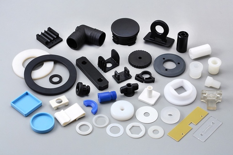
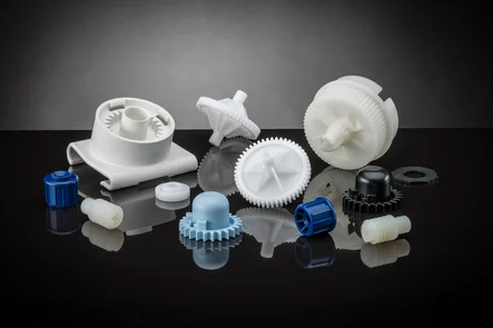
Can you provide examples of products or equipment that incorporate injection molded parts?
Yes, there are numerous products and equipment across various industries that incorporate injection molded parts. Injection molding is a widely used manufacturing process that enables the production of complex and precise components. Here are some examples of products and equipment that commonly incorporate injection molded parts:
1. Electronics and Consumer Devices:
– Mobile phones and smartphones: These devices typically have injection molded plastic casings, buttons, and connectors.
– Computers and laptops: Injection molded parts are used for computer cases, keyboard keys, connectors, and peripheral device housings.
– Appliances: Products such as televisions, refrigerators, washing machines, and vacuum cleaners often incorporate injection molded components for their casings, handles, buttons, and control panels.
– Audio equipment: Speakers, headphones, and audio players often use injection molded parts for their enclosures and buttons.
2. Automotive Industry:
– Cars and Trucks: Injection molded parts are extensively used in the automotive industry. Examples include dashboard panels, door handles, interior trim, steering wheel components, air vents, and various under-the-hood components.
– Motorcycle and Bicycle Parts: Many motorcycle and bicycle components are manufactured using injection molding, including fairings, handle grips, footrests, instrument panels, and engine covers.
– Automotive Lighting: Headlights, taillights, turn signals, and other automotive lighting components often incorporate injection molded lenses, housings, and mounts.
3. Medical and Healthcare:
– Medical Devices: Injection molding is widely used in the production of medical devices such as syringes, IV components, surgical instruments, respiratory masks, implantable devices, and diagnostic equipment.
– Laboratory Equipment: Many laboratory consumables, such as test tubes, petri dishes, pipette tips, and specimen containers, are manufactured using injection molding.
– Dental Equipment: Dental tools, orthodontic devices, and dental prosthetics often incorporate injection molded components.
4. Packaging Industry:
– Bottles and Containers: Plastic bottles and containers used for food, beverages, personal care products, and household chemicals are commonly produced using injection molding.
– Caps and Closures: Injection molded caps and closures are widely used in the packaging industry for bottles, jars, and tubes.
– Thin-Walled Packaging: Injection molding is used to produce thin-walled packaging products such as trays, cups, and lids for food and other consumer goods.
5. Toys and Games:
– Many toys and games incorporate injection molded parts. Examples include action figures, building blocks, puzzles, board game components, and remote-controlled vehicles.
6. Industrial Equipment and Tools:
– Industrial machinery: Injection molded parts are used in various industrial equipment and machinery, including components for manufacturing machinery, conveyor systems, and robotic systems.
– Power tools: Many components of power tools, such as housing, handles, switches, and guards, are manufactured using injection molding.
– Hand tools: Injection molded parts are incorporated into a wide range of hand tools, including screwdrivers, wrenches, pliers, and cutting tools.
These are just a few examples of products and equipment that incorporate injection molded parts. The versatility of injection molding allows for its application in a wide range of industries, enabling the production of high-quality components with complex geometries and precise specifications.
What eco-friendly or sustainable practices are associated with injection molding processes and materials?
Eco-friendly and sustainable practices are increasingly important in the field of injection molding. Many advancements have been made to minimize the environmental impact of both the processes and materials used in injection molding. Here’s a detailed explanation of the eco-friendly and sustainable practices associated with injection molding processes and materials:
1. Material Selection:
The choice of materials can significantly impact the environmental footprint of injection molding. Selecting eco-friendly materials is a crucial practice. Some sustainable material options include biodegradable or compostable polymers, such as PLA or PHA, which can reduce the environmental impact of the end product. Additionally, using recycled or bio-based materials instead of virgin plastics can help to conserve resources and reduce waste.
2. Recycling:
Implementing recycling practices is an essential aspect of sustainable injection molding. Recycling involves collecting, processing, and reusing plastic waste generated during the injection molding process. Both post-industrial and post-consumer plastic waste can be recycled and incorporated into new products, reducing the demand for virgin materials and minimizing landfill waste.
3. Energy Efficiency:
Efficient energy usage is a key factor in sustainable injection molding. Optimizing the energy consumption of machines, heating and cooling systems, and auxiliary equipment can significantly reduce the carbon footprint of the manufacturing process. Employing energy-efficient technologies, such as servo-driven machines or advanced heating and cooling systems, can help achieve energy savings and lower environmental impact.
4. Process Optimization:
Process optimization is another sustainable practice in injection molding. By fine-tuning process parameters, optimizing cycle times, and reducing material waste, manufacturers can minimize resource consumption and improve overall process efficiency. Advanced process control systems, real-time monitoring, and automation technologies can assist in achieving these optimization goals.
5. Waste Reduction:
Efforts to reduce waste are integral to sustainable injection molding practices. Minimizing material waste through improved design, better material handling techniques, and efficient mold design can positively impact the environment. Furthermore, implementing lean manufacturing principles and adopting waste management strategies, such as regrinding scrap materials or reusing purging compounds, can contribute to waste reduction and resource conservation.
6. Clean Production:
Adopting clean production practices helps mitigate the environmental impact of injection molding. This includes reducing emissions, controlling air and water pollution, and implementing effective waste management systems. Employing pollution control technologies, such as filters and treatment systems, can help ensure that the manufacturing process operates in an environmentally responsible manner.
7. Life Cycle Assessment:
Conducting a life cycle assessment (LCA) of the injection molded products can provide insights into their overall environmental impact. LCA evaluates the environmental impact of a product throughout its entire life cycle, from raw material extraction to disposal. By considering factors such as material sourcing, production, use, and end-of-life options, manufacturers can identify areas for improvement and make informed decisions to reduce the environmental footprint of their products.
8. Collaboration and Certification:
Collaboration among stakeholders, including manufacturers, suppliers, and customers, is crucial for fostering sustainable practices in injection molding. Sharing knowledge, best practices, and sustainability initiatives can drive eco-friendly innovations. Additionally, obtaining certifications such as ISO 14001 (Environmental Management System) or partnering with organizations that promote sustainable manufacturing can demonstrate a commitment to environmental responsibility and sustainability.
9. Product Design for Sustainability:
Designing products with sustainability in mind is an important aspect of eco-friendly injection molding practices. By considering factors such as material selection, recyclability, energy efficiency, and end-of-life options during the design phase, manufacturers can create products that are environmentally responsible and promote a circular economy.
Implementing these eco-friendly and sustainable practices in injection molding processes and materials can help reduce the environmental impact of manufacturing, conserve resources, minimize waste, and contribute to a more sustainable future.
How do injection molded parts compare to other manufacturing methods in terms of cost and efficiency?
Injection molded parts have distinct advantages over other manufacturing methods when it comes to cost and efficiency. The injection molding process offers high efficiency and cost-effectiveness, especially for large-scale production. Here’s a detailed explanation of how injection molded parts compare to other manufacturing methods:
Cost Comparison:
Injection molding can be cost-effective compared to other manufacturing methods for several reasons:
1. Tooling Costs:
Injection molding requires an initial investment in creating molds, which can be costly. However, once the molds are made, they can be used repeatedly for producing a large number of parts, resulting in a lower per-unit cost. The amortized tooling costs make injection molding more cost-effective for high-volume production runs.
2. Material Efficiency:
Injection molding is highly efficient in terms of material usage. The process allows for precise control over the amount of material injected into the mold, minimizing waste. Additionally, excess material from the molding process can be recycled and reused, further reducing material costs compared to methods that generate more significant amounts of waste.
3. Labor Costs:
Injection molding is a highly automated process, requiring minimal labor compared to other manufacturing methods. Once the molds are set up and the process parameters are established, the injection molding machine can run continuously, producing parts with minimal human intervention. This automation reduces labor costs and increases overall efficiency.
Efficiency Comparison:
Injection molded parts offer several advantages in terms of efficiency:
1. Rapid Production Cycle:
Injection molding is a fast manufacturing process, capable of producing parts in a relatively short cycle time. The cycle time depends on factors such as part complexity, material properties, and cooling time. However, compared to other methods such as machining or casting, injection molding can produce multiple parts simultaneously in each cycle, resulting in higher production rates and improved efficiency.
2. High Precision and Consistency:
Injection molding enables the production of parts with high precision and consistency. The molds used in injection molding are designed to provide accurate and repeatable dimensional control. This precision ensures that each part meets the required specifications, reducing the need for additional machining or post-processing operations. The ability to consistently produce precise parts enhances efficiency and reduces time and costs associated with rework or rejected parts.
3. Scalability:
Injection molding is highly scalable, making it suitable for both low-volume and high-volume production. Once the molds are created, the injection molding process can be easily replicated, allowing for efficient production of identical parts. The ability to scale production quickly and efficiently makes injection molding a preferred method for meeting changing market demands.
4. Design Complexity:
Injection molding supports the production of parts with complex geometries and intricate details. The molds can be designed to accommodate undercuts, thin walls, and complex shapes that may be challenging or costly with other manufacturing methods. This flexibility in design allows for the integration of multiple components into a single part, reducing assembly requirements and potential points of failure. The ability to produce complex designs efficiently enhances overall efficiency and functionality.
5. Material Versatility:
Injection molding supports a wide range of thermoplastic materials, providing versatility in material selection based on the desired properties of the final part. Different materials can be chosen to achieve specific characteristics such as strength, flexibility, heat resistance, chemical resistance, or transparency. This material versatility allows for efficient customization and optimization of part performance.
In summary, injection molded parts are cost-effective and efficient compared to many other manufacturing methods. The initial tooling costs are offset by the ability to produce a large number of parts at a lower per-unit cost. The material efficiency, labor automation, rapid production cycle, high precision, scalability, design complexity, and material versatility contribute to the overall cost-effectiveness and efficiency of injection molding. These advantages make injection molding a preferred choice for various industries seeking to produce high-quality parts efficiently and economically.
editor by CX 2024-01-15
China Made in Italy LN pawl torque limiter Eurocardan cardanic shaft PTO agricultural machinery electric screwdriver torque limiter
Guarantee: 3 many years
Relevant Industries: Agricultural machinery
Custom-made assistance: OEM
Framework: Double
Materials: Other
Functioning Angle: –
Offered torque [Nm]: 380-1900
Offered dimension: 1-6
Protection device type: Pawl limiter
Packaging Particulars: wood crate
Port: Salerno, Italy
Merchandise Description The LN torque limiter is a unit that boundaries the torque many thanks to radial action pawls which operate countered by the resistance supplied by coil springs. Transmission reset is automatic when the number of revolutions is diminished. When the torque transmitted exceeds the pre-established calibration value, the pawls escape from their seats, beating the resistance offered by 1 or 2 coil springs.At the time of the intervention, the LN limiter interrupts power transmission, minimizing the torque transmitted to a minimum price essential for successive reset, which requires location instantly when the amount of revs. is decreased. The benefit of the torque environment is pre-set in the manufacturing unit based on the quantity of rows of pawls and the configuration of the springs. Thanks to the residual torque instant decreased to a bare minimum, overheating and vibration during intervention are also decreased. Unique design and style on request. It operates in the two instructions of rotation considering that the pawls are symmetrical. * Unique design on ask for Molded CZPT Processing Services Customized Pin Gate Injection Molding For Ab muscles Shell * It functions in equally directions of rotation since the pawls are symmetrical. Firm Profile Power on the transferEurocardan was launched in 1982 in get to meet the requirements of makers of agricultural equipment who ended up hunting for dependable driveshafts for their goods, created by a company that could really realize their needs with integrity and professionalism. Eurocardan has always stood out for the outstanding trustworthiness of its merchandise and for its ability to recognize market needs, giving a extensive variety of high top quality and large-efficiency items.The CZPT GroupBehind the most CZPT businesses there is often a successful group that supports and improves it. The CZPT Team is a household-operate business where the whole management consists of men and women who have been born and consistently live in the company philosophy of ethics, respect, commitment to perform and professionalism. This team combines the protagonists of the market place of agricultural equipment and their elements. Sicma S.p.A., the flagship firm of the team, is dependent on the technologies and perfection of the cardanic programs developed and produced by Eurocardan S.p.A., 1 of the most CZPT European businesses of the cardan sector. Getting able to depend on Alfametal, GICLZ Unilateral tooth Drum equipment coupling a department of large professional carpentry that operates within and on behalf of Sicma and Eurocardan, is a gain that enables more successful control of the complete manufacturing chain, guaranteeing virtually unrivalled high quality in the sector. Operating with ethics has imposed on the CZPT Team the idea of functioning while respecting the environmental and vitality-preserving guidelines, thus encouraging the creation of CZPT Energy that addresses the use of renewable sources by exploiting the hundreds of square CZPT occupied by the companies of the group to generate clear energy from the solar and making use of it for production purposes. Our Positive aspects 40 Several years OF INNOVATION“For practically 40 many years, through a technically sophisticated producing system which completely embraces the CZPT of “Full Manufactured in Italy”, Supply factory manufacture linear information rail and block Eurocardan’s mission has been to develop driveshafts for each agricultural and industrial uses, and aimed at specialist purposes through the world.” Certifications Certified Eurocardan qualityISO 9001:2015 certification was awarded for the management and operational processes that permeate the complete Eurocardanorganisation: it commences with the design which is strengthened by the transformation of the resources and ends in Good quality Controland Tests. Eurocardan merchandise also comply with the following expectations: * DIR 2006/42/CE * CZPT EN 12965:2007 * CZPT EN ISO 5674:2007The search for CZPT is seen in the teamwork done in every single division at Eurocardan: the principal objective is to provide a support that exceeds the customer’s anticipations. Packaging Make contact with Us Eurocardan S.p.a.Via Firenze, 25, 66041 Atessa (CH) ITALYEurocardan is located in Atessa (CH), in the industrial spot of Val di Sangro. It is simply reachable in less than an hour from Pescara (motorway A14, CE accepted higher obligation planetary 60L foodstuff mixer exit Val di Sangro), the place there is the airport ofAbruzzo, the airport of the region that connects the latter with the most important Italian and European metropolitan areas.Tel. +1Fax +39 571.897200Email [email protected]

Types of Torque Limiters
Regardless of the type of application, there are several types of torque limiters available. Some of these types include Ball detent limiters, Hydraulic torque limiters, and Magnetic torque limiters.
Ball detent limiter
Typically, the ball detent torque limiter is used in applications where precision is essential. For example, in packaging or textile applications, the detent can limit the amount of torque transmitted from the input gear to the output gear. In some applications, the torque limiter is a preferable option over a slip clutch.
The basic ball detent mechanism involves a series of metal balls encased in two circular plates. The balls are held in place by springs. In normal operation, the balls rest in sockets within a pressure flange. However, in an overload situation, the balls are forced out of the sockets and into the detents. The balls are then forced back into the sockets by the springs. This action continues until the overload is removed.
The ball detent torque limiter has a unique design that provides reliable overload protection. The balls are held in place by springs and the assembly rotates with the driven machine until an overload occurs.
The balls are sized to maintain a predetermined axial separation distance between the driving surface of the input gear and the detent surface of the backing plate. This axial separation distance is greater than the diameter of the primary balls. When an overload is sensed, the springs disengage the balls and the ball detent torque limiter releases the load.
In addition to the ball detent torque limiter, there are several other types of torque limiters. Some of them are simple shear pins or cam followers, while others are pneumatically engaged. These types of torque limiters can be used in conjunction with limit switches.
The ball detent torque limiter may be manually engaged when the over-torque condition is corrected. The limit switch can be manually activated or can be automatically triggered by a proximity sensor.
Torque limiters can be used to prevent physical injury to personnel and damage to sensitive equipment. They are available in various designs, including single-position and multi-position units. Many servo-driven axes are equipped with these devices. They are commonly used in mechanical wastewater treatment plants and in chain couplings.
Unlike other torque limiters, the ball detent torque limiter can accurately disengage at the preset torque value. It also has a more predictable response time than other types of torque limiters.
Magnetic torque limiter
Using a torque limiter in conjunction with a motor can be a tricky business. It requires an understanding of the mechanical gearbox and torque limiter and how they work together to reduce mechanical vibrations and achieve the correct torque levels.
A torque limiter is a simple device that transmits torque through magnetic interaction. It is a useful device for measuring and controlling the tightening of implantable medical devices such as screws and plates. Magnetic torque limiters offer several advantages over conventional devices, including increased durability and reliability. They can be sterilized and are easy to clean. In addition, they require little maintenance and are not prone to wear and tear.
Magnetic torque limiters have two main components: a handle with a cylindrical body and a mono-block shaft. The handle has an arm that enables it to be adjusted and the shaft has an arm bearing to make it movable. The handle may be used on shafts with different drive geometries.
The handle has a rotating collar that is indexed with ball detents to allow it to be adjusted. The collar is user-accessible and has the capacity to do more than just compress or extend the torque limit. It can also be used to change the gap between the two magnets in the handle.
The main component of the magnetic torque limiter is the handle, which includes a pair of magnets with opposing poles. This configuration has the magnetic effect of generating a torque from the magnetic hysteresis resistance of the magnets. The magnets are linked together by metal pins, which can be replaced.
The first pocket (4) is located on the first side of the cylindrical handle-body. The second pocket (5) is located on the second side. Both pockets contain at least one magnet, preferably a neodymium magnet. The pocket on the first side intersects the second pocket on the second side in the central through bore. The main objective of this pocket is to transmit the smallest possible torque from the input to the output.
The best way to find out how the magnetic torque limiter of the present invention performs is to put it to the test. Several tests have been conducted to determine its performance. The results show that it translates 24 Nm at a nominal speed of 2500 rpm from the input to the output.
Hydraulic torque limiter
Using a Hydraulic Torque Limiter to protect equipment from excessive torque is beneficial in many applications. These devices are a safe way to maintain maximum torque in a power transmission system. They are available in many different types, and can be used in practically any application.
They are able to protect from excessive torque by controlling the flow of gas and hydraulic fluid in the drive system. They are used in various applications, such as conveyors, assembly lines, and industrial robots. They are used to protect equipment from overloads, and assure minimal downtime.
They are also used in applications where the driven device cannot absorb all of the output torque. The torque limiter transfers the torque from the driving shaft to the driven member. The torque limiter is also used to couple gears, sprockets, and other rotating bodies. The torque limiter transmits torque at a specified level, and stops transmitting when the torque exceeds a preset value.
Torque limiters are generally light-weight, and can be easily mounted. However, they can present a safety hazard to operating personnel. They are used in many different industries, including textile, woodworking, printing, and converting machinery.
The torque limiter is used to disconnect the inertia of the system from the jammed section, which prevents damage. In this instance, the limiter is placed as close as possible to the jam source.
Torque limiters operate by comparing the internal pressures in a hydraulic cylinder. When the pressures exceed a specified value, the torque limiter stops transmitting and begins disengaging the driven device.
These devices also allow for the use of smaller prime movers and less fuel. They can also be used to prevent stalling of the prime mover under heavy loads.
Torque limiters are available in a variety of sizes and are typically used in applications where the driven device cannot absorb all of the output torque. They are used in many industrial robots, conveyors, assembly lines, and printing and converting machinery.
Torque limiters are available in mechanical, hydraulic, and synchronous magnetic types. Some of them can tolerate continuous slip, but some are designed to slip at a specified torque value.
CZPT Electric torque limiter
Whether you need an industrial clutch, electromagnetic brake, or torque limiter, CZPT Electric has a solution for you. This company offers the broadest range of industrial products and brakes, as well as customized solutions for your application. The company’s products are used across a wide range of industries, including material handling, crane and motion control, elevator and escalator, forklift, turf and garden, marine propulsion, and sewage pumps.
It has a large sales and distribution operation in North America, and is available in over 70 countries. The company’s products are designed to meet industrial demands for quality, performance, and reliability. Its line of Adjustable Torque Controls are designed to provide soft starting functions, as well as repeatable stops.
Torque limiters are used in many different industries, including steel mills, conveyor drives, process pumps, marine propulsion, and paper mills. They are designed to separate the load from the drive when an overload occurs. They offer both mechanical and electronic solutions, and are available in an open or closed design. They can operate at a range of 160 to 11,000 rpm. They also feature a shear neck, fail-safe, wedge-shaped construction, and clamping screws. They are available with RoHS compliant options, as well as CE certified.
These limiters also feature a proximity sensor target that can be used to switch off the drive after an overload. CZPT Electric has several models with full range torque control, which provides repeatable starts and stops. They can also be used with electrically released brakes. The company also offers a variety of clutch/brake combinations, including a wide selection of models with a ball detent or synchronous magnetic disconnect.
CZPT Electric’s products are manufactured to a high standard and are designed to meet the demands of today’s industrial applications. The company has a wide range of product catalogues available for browsing. You can find a list of available products and more information on the company’s website, which can be accessed by clicking on the “Product Catalogues” button at the bottom of the page.

editor by Cx2023-07-13
China Good quality forged tractor pto shaft agricultural machinery parts ffvss2 ratchet clutches pto shaft friction clutch torque limiter chain coupling
Issue: New
Warranty: 1 12 months
Relevant Industries: Lodges, Garment Shops, Developing Materials Stores, Production Plant, Equipment Repair Retailers, Foods & Beverage Manufacturing facility, Farms, Cafe, Home Use, Retail, Foods Store, Printing Retailers, Construction works , Vitality & Mining, Foods & Beverage Shops, Other, Advertising and marketing Firm
Fat (KG): ten KG
Showroom Place: None
Online video outgoing-inspection: Presented
Equipment Take a look at Report: Supplied
Marketing Kind: Normal Merchandise
Kind: Limiter
Use: PTO Shaft
Product Name: equipment elements ffvss2 ratchet clutches pto shaft friction clutch
Disc: two
Color: black
Diameter: 200
Friction Diameter: a hundred and sixty
Method: Forging
Mould: FFVS2
Male Spline: 1 3/8” Z6
Certification: ISO & CE
Female Spline: 1 3/8” Z6
Packaging Details: Plastic bag+ Woodencase + According to Customer’s ask for
Port: ZheJiang or HangZhou
| Model Variety | FFVS2 Friction Torque Limiter |
| Function | Drive Shaft Elements & Electricity Transmission |
| Use | Kinds of Tractors & Farm Implements |
| Brand Title | 9K |
| Yoke Type | Double push pin,Bolt pins, velocity reducer Agricultural gearbox G18 rotary tedders Break up pins,Push pin,Quick launch,Ball attachment,Collar….. |
| Processing Of Yoke | Forging |
| Plastic Include | YWBWYSBSEtc |
| Color | GreenOrangeYellowBlack Ect. |
| Series | T1-T10 L1-L6S6-S1010HP-150HP with SA,RA,SB,SFF,WA,CV And many others |
| Tube Variety | Lemon, CZPT gearbox Appropriate Angle 90 diploma Agriculture Farm Tractor Rotary cutter Mower Bevel Agricultura BUGH HOGl Gearbox Trianglar,Star,Square,Hexangular,Spline,Unique Ect |
| Processing Of Tube | Cold drawn |
| Spline Sort | 1 1/8″ Z61 3/8″ Z6 1 3/8″ Z21 1 3/4″ Z20 1 3/4″ Z6 8-38*32*6 8-forty two*36*7 8-48*42*eight |
| Place of Origin | HangZhou, China (Mainland) |

What Is a Torque Limiter?
Whether you’re looking to add an extra bit of torque to your tool, or simply to keep the torque from getting out of hand, a limiter is a good tool to have on hand. There are a number of different limiters to choose from, including Ball detent limiters, Synchronous magnetic limiters, and Friction torque limiters.
Ball detent limiter
Typically, ball detent torque limiters use balls or rollers in sockets to control torque and force transmission through the load path. They are suitable for applications that require high precision and a fast response. They also minimize the possibility of damage caused by high-inertia loads. These torque limiters are often used on servo-driven axes. They are also suitable for packaging and woodworking.
A torque-limiting assembly consists of a gear, a cage, a series of balls, a spring, and breakout means. A cage is mounted between the input gear and a fixed backing plate. The cage rotates through half of the input gear’s axial angle. The cage holds the primary balls. When torque overload occurs, the primary balls roll out of their pockets and force the drive and driven elements to separate.
The cage also increases the frictional resistance to relative rotation. During normal torque loading, the primary balls continue to roll on the flat driving surface of the input gear. The cage displaces the input gear against the bias of the spring. This action maintains the assembly in this arrangement. The cage then rotates through the other half of the input gear’s axial angle. When the primary balls roll out of their pockets, the cage is forced axially toward the fixed backing plate.
The cage also has a secondary ball stop, which limits the travel of the secondary balls. Secondary balls are seated in terminal positions on the input gear. These balls roll out of secondary ball pockets 68 and 70. They may also be positioned in terminal positions. The secondary balls travel over ramps 69 and 72. They are sized to maintain a axial separation distance between the driving surface and the detent surface.
The primary balls are seated in the primary ball pockets 40 and 50 in the driving surface of the input gear. The cap projects into the primary ball pockets 50 in the detent surface 48. A plurality of secondary balls are seated in secondary ball pockets 68 and 70 in the driven surface of the cage. This action prevents the input gear from being displaced by the spring 20.
Friction torque limiter
Essentially a shaft-to-shaft coupling, a friction torque limiter combines economy and simplicity. The unit is designed to protect against excessive torque and also prevent damage from overloads. Typically used in conjunction with other drive components, a torque limiter is easy to install and replace, providing simple, cost-effective protection.
Torque limiters are available in many formats, including basic shear pins, ball detent units, and pneumatic controls. Each type of torque limiter must be designed for a specific application. Some systems offer a single position device, while others allow the operator to adjust settings to prevent overloads.
Torque limiters are commonly used in a wide variety of applications, including conveyors, sewage treatment plants, and power stations. These devices provide simple, cost-effective overload protection, and can be used in both directions of torque transmission.
Friction torque limiters are ideal for applications that operate under dusty conditions. They are also more predictable than shear pins, and can be adjusted to a variety of torque levels. The H-diameter calibration system on a GEC model, for example, makes it easier to determine the best torque setting for a given application.
Torque limiters can be coupled to any combination of rotating bodies, including shafts, pulleys, gears, and motors. They can be adjusted with an adjustable nut, and a variety of spring sets can be fitted to provide different torque ranges.
Torque limiters may also be equipped with a limit switch, which permits control of the motor drive system. If a torque overload occurs, the limit switch will signal the control system to shut the motor off.
Torque limiters are usually made from durable heat-treated steel. Some models come with bronze bushings for additional protection, and some offer a random reset device. To determine which torque limiter is right for your application, consult a factory. Regardless of the type of torque limiter you choose, it should have the right torque range and the right bore size.
In addition to preventing overloads, friction torque limiters can also help prevent damage to drive components, especially when they are used in conjunction with gears, sprockets, and pulleys. They are also simple to install and replace, providing simple, cost-effective, and user-friendly protection.
Reset style of limiter
Depending on the application, there are several styles of torque limiters. It is a good idea to consult a manufacturer in your area for the specifics. You’ll also want to make sure your new tool is the most effective fit for your application. A good rule of thumb is to match the output of your machine to the inputs of your torque limiter.
A good torque limiter should offer the following: a minimum of lost motion, a low frictional drag, and a low operating temperature. Some manufacturers offer a host of options, including a variety of materials and sizes. It is also worthwhile to select a torque limiter based on its mounting surface. Ideally, you want it to sit as close to the output of the machine as possible.
The best torque limiters are not only clever, they also offer a high degree of safety and reliability. They come in several varieties, from a simple pawl and spring configuration to hydraulic pressure and pneumatic pressure to complex synchronous magnetic and synchronous magnetic coupled units. Choosing the right one for your application can make a world of difference, especially if you want to make sure your equipment runs smoothly and efficiently.
One notable exception is a hydraulic torque limiter, which is seldom used for a simple reason: they’re too expensive. They are a bit complicated, and tend to occupy much more space than their petrochemical cousins. They also tend to require a lot of maintenance, especially if you’re dealing with a corrosive environment. The biggest disadvantage is that they often do not work well in high-stress environments. Fortunately, there are more cost-effective solutions to this problem. You should also know that a torque limiter is a safety device, so you should make sure to use one. This type of equipment is also useful in correcting misalignment and parallelism errors, so you’ll want to be sure you’re putting it to good use.
A torque limiter is a safety device that must decouple from the driven device when overload is detected. They are a worthwhile investment, and can be a useful tool in correcting misalignment and parallelism mistakes, ensuring your machine runs smoothly and safely.
Synchronous magnetic torque limiter
Basically, a torque limiter is a device that is used to limit the torque of the system. It protects the mechanical system of the machine from overload and damage. These devices are usually integrated into the drive train of a table-based machine or hand tool. In some cases, they may be reset automatically, while others need to be reset manually.
There are two kinds of torque limiters: the mechanical and the disconnect. In the mechanical type, a spring or a pawl is used to limit the torque. In the disconnect type, a mechanical component is sacrificed to allow the torque limiter to disconnect the drive. The disconnect type may be reset manually, while some may need to be reset automatically.
The synchronous magnetic torque limiter is a type of limiter that uses two magnets on each shaft of the machine. This type of limiter has some advantages over mechanical types, but there are also disadvantages. For example, it may have more backlash than the mechanical types. It may also transmit torque through a physical barrier. These disadvantages are sometimes offset by the fact that the synchronous magnetic torque limiter is able to work quickly and smoothly.
The torque limiter is usually the last gearset installed in a transmission assembly. It protects mechanical systems from overload and prevents the engine from burning out. Some types of torque limiters may require adjustment, but most of them do not. A torque limiter can be found in many cordless drills. Often, the torque limiter is positioned inside the planetary gearset.
The variable magnetic gearbox is another type of torque limiter. This type is a rotational device that uses a variable ratio magnetic gear. The variable magnetic gearbox uses about 25% of the input power and has lower maintenance requirements. It also has a lower output torque. It can be used to effectively limit the torque of a system.
A magnetic particle clutch can also be used as a torque limiter. This type of limiter is similar to the friction plate clutch. It can be integrated into a cylinder head. This type of clutch can be dynamically set or statically set.
editor by Cx2023-07-13
China 6 tons folding arm hydraulic small crane construction machinery factory direct sale low price hot sale dalton torque limiter
Attribute: TRUCK CRANE
Showroom Place: None
Problem: New
Software: ~4 engine Belt Tensioner pulley pickup crane,aerial system truck,marine crane. 2) Which variety of payment you can be accepted?Generally each of T/T & L/C at sight are okay for us.Alibaba trade assurance,credit history card, Skid Steer LoaderExcavator Hedge Trimmer Blade Grinding Machine Blade Sharp Durable Gardening Hedge Trimmer western union. 3) How about the supply time?20-forty doing work days after acquired thirty% T/T or L/C.70% stability payment before delivery. 4) What is your warranty?Usually is 1 yr, if huge quantities we can negotiate.We will mail the equipment to you for cost-free if have difficulties within 1 yr. 5) What is actually your MOQ?MOQ: 1 established 6) Can you acknowledge OEM service?Of course for sure my good friend.We give brand,package, Kayak Paddle Grips Protect Neoprene Paddle Shaft Oar Include Comfortable Safeguard Hand Blister Prevention Accessories Kayak Gear for Men and custom-made,and also can personalized the product in accordance to your needs. 7) Optional Attachment?Distant Manage, Basket, Auger, Grapple, CZPT KVP04 cheap mini oil cost-free dry working circulation brushless motor damaging stress suction pump Best Seat, Rear outriggers Make contact with Us Product sales Manager:Sophie TEL/WhatsApp:1505057190E-mail:[email protected]
Types of Torque Limiters
Regardless of the type of application, there are several types of torque limiters available. Some of these types include Ball detent limiters, Hydraulic torque limiters, and Magnetic torque limiters.
Ball detent limiter
Typically, the ball detent torque limiter is used in applications where precision is essential. For example, in packaging or textile applications, the detent can limit the amount of torque transmitted from the input gear to the output gear. In some applications, the torque limiter is a preferable option over a slip clutch.
The basic ball detent mechanism involves a series of metal balls encased in two circular plates. The balls are held in place by springs. In normal operation, the balls rest in sockets within a pressure flange. However, in an overload situation, the balls are forced out of the sockets and into the detents. The balls are then forced back into the sockets by the springs. This action continues until the overload is removed.
The ball detent torque limiter has a unique design that provides reliable overload protection. The balls are held in place by springs and the assembly rotates with the driven machine until an overload occurs.
The balls are sized to maintain a predetermined axial separation distance between the driving surface of the input gear and the detent surface of the backing plate. This axial separation distance is greater than the diameter of the primary balls. When an overload is sensed, the springs disengage the balls and the ball detent torque limiter releases the load.
In addition to the ball detent torque limiter, there are several other types of torque limiters. Some of them are simple shear pins or cam followers, while others are pneumatically engaged. These types of torque limiters can be used in conjunction with limit switches.
The ball detent torque limiter may be manually engaged when the over-torque condition is corrected. The limit switch can be manually activated or can be automatically triggered by a proximity sensor.
Torque limiters can be used to prevent physical injury to personnel and damage to sensitive equipment. They are available in various designs, including single-position and multi-position units. Many servo-driven axes are equipped with these devices. They are commonly used in mechanical wastewater treatment plants and in chain couplings.
Unlike other torque limiters, the ball detent torque limiter can accurately disengage at the preset torque value. It also has a more predictable response time than other types of torque limiters.
Magnetic torque limiter
Using a torque limiter in conjunction with a motor can be a tricky business. It requires an understanding of the mechanical gearbox and torque limiter and how they work together to reduce mechanical vibrations and achieve the correct torque levels.
A torque limiter is a simple device that transmits torque through magnetic interaction. It is a useful device for measuring and controlling the tightening of implantable medical devices such as screws and plates. Magnetic torque limiters offer several advantages over conventional devices, including increased durability and reliability. They can be sterilized and are easy to clean. In addition, they require little maintenance and are not prone to wear and tear.
Magnetic torque limiters have two main components: a handle with a cylindrical body and a mono-block shaft. The handle has an arm that enables it to be adjusted and the shaft has an arm bearing to make it movable. The handle may be used on shafts with different drive geometries.
The handle has a rotating collar that is indexed with ball detents to allow it to be adjusted. The collar is user-accessible and has the capacity to do more than just compress or extend the torque limit. It can also be used to change the gap between the two magnets in the handle.
The main component of the magnetic torque limiter is the handle, which includes a pair of magnets with opposing poles. This configuration has the magnetic effect of generating a torque from the magnetic hysteresis resistance of the magnets. The magnets are linked together by metal pins, which can be replaced.
The first pocket (4) is located on the first side of the cylindrical handle-body. The second pocket (5) is located on the second side. Both pockets contain at least one magnet, preferably a neodymium magnet. The pocket on the first side intersects the second pocket on the second side in the central through bore. The main objective of this pocket is to transmit the smallest possible torque from the input to the output.
The best way to find out how the magnetic torque limiter of the present invention performs is to put it to the test. Several tests have been conducted to determine its performance. The results show that it translates 24 Nm at a nominal speed of 2500 rpm from the input to the output.
Hydraulic torque limiter
Using a Hydraulic Torque Limiter to protect equipment from excessive torque is beneficial in many applications. These devices are a safe way to maintain maximum torque in a power transmission system. They are available in many different types, and can be used in practically any application.
They are able to protect from excessive torque by controlling the flow of gas and hydraulic fluid in the drive system. They are used in various applications, such as conveyors, assembly lines, and industrial robots. They are used to protect equipment from overloads, and assure minimal downtime.
They are also used in applications where the driven device cannot absorb all of the output torque. The torque limiter transfers the torque from the driving shaft to the driven member. The torque limiter is also used to couple gears, sprockets, and other rotating bodies. The torque limiter transmits torque at a specified level, and stops transmitting when the torque exceeds a preset value.
Torque limiters are generally light-weight, and can be easily mounted. However, they can present a safety hazard to operating personnel. They are used in many different industries, including textile, woodworking, printing, and converting machinery.
The torque limiter is used to disconnect the inertia of the system from the jammed section, which prevents damage. In this instance, the limiter is placed as close as possible to the jam source.
Torque limiters operate by comparing the internal pressures in a hydraulic cylinder. When the pressures exceed a specified value, the torque limiter stops transmitting and begins disengaging the driven device.
These devices also allow for the use of smaller prime movers and less fuel. They can also be used to prevent stalling of the prime mover under heavy loads.
Torque limiters are available in a variety of sizes and are typically used in applications where the driven device cannot absorb all of the output torque. They are used in many industrial robots, conveyors, assembly lines, and printing and converting machinery.
Torque limiters are available in mechanical, hydraulic, and synchronous magnetic types. Some of them can tolerate continuous slip, but some are designed to slip at a specified torque value.
CZPT Electric torque limiter
Whether you need an industrial clutch, electromagnetic brake, or torque limiter, CZPT Electric has a solution for you. This company offers the broadest range of industrial products and brakes, as well as customized solutions for your application. The company’s products are used across a wide range of industries, including material handling, crane and motion control, elevator and escalator, forklift, turf and garden, marine propulsion, and sewage pumps.
It has a large sales and distribution operation in North America, and is available in over 70 countries. The company’s products are designed to meet industrial demands for quality, performance, and reliability. Its line of Adjustable Torque Controls are designed to provide soft starting functions, as well as repeatable stops.
Torque limiters are used in many different industries, including steel mills, conveyor drives, process pumps, marine propulsion, and paper mills. They are designed to separate the load from the drive when an overload occurs. They offer both mechanical and electronic solutions, and are available in an open or closed design. They can operate at a range of 160 to 11,000 rpm. They also feature a shear neck, fail-safe, wedge-shaped construction, and clamping screws. They are available with RoHS compliant options, as well as CE certified.
These limiters also feature a proximity sensor target that can be used to switch off the drive after an overload. CZPT Electric has several models with full range torque control, which provides repeatable starts and stops. They can also be used with electrically released brakes. The company also offers a variety of clutch/brake combinations, including a wide selection of models with a ball detent or synchronous magnetic disconnect.
CZPT Electric’s products are manufactured to a high standard and are designed to meet the demands of today’s industrial applications. The company has a wide range of product catalogues available for browsing. You can find a list of available products and more information on the company’s website, which can be accessed by clicking on the “Product Catalogues” button at the bottom of the page.
editor by Cx2023-07-13
China Made in Italy LN pawl torque limiter Eurocardan cardanic shaft PTO agricultural machinery electric torque limiter
Warranty: 3 several years
Relevant Industries: Agricultural machinery
Customized assist: OEM
Construction: Double
Substance: Other
Running Angle: –
Available torque [Nm]: 380-1900
Accessible measurement: 1-six
Protection unit kind: Pawl limiter
Packaging Particulars: wood crate
Port: Salerno, Italy
Products Description The LN torque limiter is a device that boundaries the torque many thanks to radial motion pawls which function countered by the resistance provided by coil springs. Transmission reset is automatic when the amount of revolutions is decreased. When the torque transmitted exceeds the pre-set calibration worth, the pawls escape from their seats, conquering the resistance offered by 1 or 2 coil springs.At the time of the intervention, the LN limiter interrupts electrical power transmission, decreasing the torque transmitted to a least value required for successive reset, which normally takes location automatically when the number of revs. is diminished. The value of the torque setting is pre-set in the factory depending on the amount of rows of pawls and the configuration of the springs. Thanks to the residual torque second lowered to a minimal, overheating and vibration throughout intervention are also reduced. Special style on request. It performs in the two directions of rotation because the pawls are symmetrical. * Unique design and style on request Molded CZPT Processing Support Customized Pin Gate Injection Molding For Abdominal muscles Shell * It functions in each instructions of rotation given that the pawls are symmetrical. Firm Profile Energy on the goEurocardan was started in 1982 in order to satisfy the demands of producers of agricultural machinery who had been hunting for trustworthy driveshafts for their items, created by a company that could truly recognize their wants with integrity and professionalism. Eurocardan has constantly stood out for the superior reliability of its items and for its capacity to understand marketplace requirements, giving a wide selection of substantial quality and higher-efficiency merchandise.The CZPT GroupBehind the most CZPT businesses there is often a profitable team that supports and improves it. The CZPT Team is a loved ones-operate business in which the complete administration is composed of men and women who ended up born and continuously live in the company philosophy of ethics, respect, devotion to perform and professionalism. This team combines the protagonists of the marketplace of agricultural equipment and their elements. Sicma S.p.A., the flagship company of the team, is dependent on the engineering and perfection of the cardanic techniques made and created by Eurocardan S.p.A., 1 of the most CZPT European businesses of the cardan sector. Being able to depend on Alfametal, GICLZ Unilateral tooth Drum gear coupling a office of large specialist carpentry that operates in and on behalf of Sicma and Eurocardan, is a gain that permits a lot more successful control of the complete manufacturing chain, guaranteeing virtually unrivalled quality in the sector. Doing work with ethics has imposed on the CZPT Group the principle of working even though respecting the environmental and strength-conserving policies, as a result encouraging the development of CZPT Power that addresses the use of renewable resources by exploiting the countless numbers of square CZPT occupied by the companies of the team to create clean power from the solar and utilizing it for generation purposes. Our Positive aspects 40 Several years OF INNOVATION“For virtually forty a long time, by means of a technically sophisticated manufacturing program which completely embraces the CZPT of “Full Created in Italy”, Resource manufacturing facility manufacture linear manual rail and block Eurocardan’s mission has been to construct driveshafts for the two agricultural and industrial makes use of, and aimed at specialist applications through the world.” Certifications Accredited Eurocardan qualityISO 9001:2015 certification was awarded for the management and operational procedures that permeate the complete Eurocardanorganisation: it begins with the style which is strengthened by the transformation of the resources and finishes in Quality Controland Tests. Eurocardan goods also comply with the adhering to expectations: * DIR 2006/forty two/CE * CZPT EN 12965:2007 * CZPT EN ISO 5674:2007The lookup for CZPT is seen in the teamwork carried out in each section at Eurocardan: the major objective is to supply a provider that exceeds the customer’s expectations. Packaging Make contact with Us Eurocardan S.p.a.Via Firenze, 25, 66041 Atessa (CH) ITALYEurocardan is found in Atessa (CH), in the industrial spot of Val di Sangro. It is simply reachable in much less than an hour from Pescara (motorway A14, CE accepted large responsibility planetary 60L meals mixer exit Val di Sangro), where there is the airport ofAbruzzo, the airport of the area that connects the latter with the most important Italian and European towns.Tel. +1Fax +39 571.897200Email [email protected]
Types of Torque Limiters
Regardless of the type of application, there are several types of torque limiters available. Some of these types include Ball detent limiters, Hydraulic torque limiters, and Magnetic torque limiters.
Ball detent limiter
Typically, the ball detent torque limiter is used in applications where precision is essential. For example, in packaging or textile applications, the detent can limit the amount of torque transmitted from the input gear to the output gear. In some applications, the torque limiter is a preferable option over a slip clutch.
The basic ball detent mechanism involves a series of metal balls encased in two circular plates. The balls are held in place by springs. In normal operation, the balls rest in sockets within a pressure flange. However, in an overload situation, the balls are forced out of the sockets and into the detents. The balls are then forced back into the sockets by the springs. This action continues until the overload is removed.
The ball detent torque limiter has a unique design that provides reliable overload protection. The balls are held in place by springs and the assembly rotates with the driven machine until an overload occurs.
The balls are sized to maintain a predetermined axial separation distance between the driving surface of the input gear and the detent surface of the backing plate. This axial separation distance is greater than the diameter of the primary balls. When an overload is sensed, the springs disengage the balls and the ball detent torque limiter releases the load.
In addition to the ball detent torque limiter, there are several other types of torque limiters. Some of them are simple shear pins or cam followers, while others are pneumatically engaged. These types of torque limiters can be used in conjunction with limit switches.
The ball detent torque limiter may be manually engaged when the over-torque condition is corrected. The limit switch can be manually activated or can be automatically triggered by a proximity sensor.
Torque limiters can be used to prevent physical injury to personnel and damage to sensitive equipment. They are available in various designs, including single-position and multi-position units. Many servo-driven axes are equipped with these devices. They are commonly used in mechanical wastewater treatment plants and in chain couplings.
Unlike other torque limiters, the ball detent torque limiter can accurately disengage at the preset torque value. It also has a more predictable response time than other types of torque limiters.
Magnetic torque limiter
Using a torque limiter in conjunction with a motor can be a tricky business. It requires an understanding of the mechanical gearbox and torque limiter and how they work together to reduce mechanical vibrations and achieve the correct torque levels.
A torque limiter is a simple device that transmits torque through magnetic interaction. It is a useful device for measuring and controlling the tightening of implantable medical devices such as screws and plates. Magnetic torque limiters offer several advantages over conventional devices, including increased durability and reliability. They can be sterilized and are easy to clean. In addition, they require little maintenance and are not prone to wear and tear.
Magnetic torque limiters have two main components: a handle with a cylindrical body and a mono-block shaft. The handle has an arm that enables it to be adjusted and the shaft has an arm bearing to make it movable. The handle may be used on shafts with different drive geometries.
The handle has a rotating collar that is indexed with ball detents to allow it to be adjusted. The collar is user-accessible and has the capacity to do more than just compress or extend the torque limit. It can also be used to change the gap between the two magnets in the handle.
The main component of the magnetic torque limiter is the handle, which includes a pair of magnets with opposing poles. This configuration has the magnetic effect of generating a torque from the magnetic hysteresis resistance of the magnets. The magnets are linked together by metal pins, which can be replaced.
The first pocket (4) is located on the first side of the cylindrical handle-body. The second pocket (5) is located on the second side. Both pockets contain at least one magnet, preferably a neodymium magnet. The pocket on the first side intersects the second pocket on the second side in the central through bore. The main objective of this pocket is to transmit the smallest possible torque from the input to the output.
The best way to find out how the magnetic torque limiter of the present invention performs is to put it to the test. Several tests have been conducted to determine its performance. The results show that it translates 24 Nm at a nominal speed of 2500 rpm from the input to the output.
Hydraulic torque limiter
Using a Hydraulic Torque Limiter to protect equipment from excessive torque is beneficial in many applications. These devices are a safe way to maintain maximum torque in a power transmission system. They are available in many different types, and can be used in practically any application.
They are able to protect from excessive torque by controlling the flow of gas and hydraulic fluid in the drive system. They are used in various applications, such as conveyors, assembly lines, and industrial robots. They are used to protect equipment from overloads, and assure minimal downtime.
They are also used in applications where the driven device cannot absorb all of the output torque. The torque limiter transfers the torque from the driving shaft to the driven member. The torque limiter is also used to couple gears, sprockets, and other rotating bodies. The torque limiter transmits torque at a specified level, and stops transmitting when the torque exceeds a preset value.
Torque limiters are generally light-weight, and can be easily mounted. However, they can present a safety hazard to operating personnel. They are used in many different industries, including textile, woodworking, printing, and converting machinery.
The torque limiter is used to disconnect the inertia of the system from the jammed section, which prevents damage. In this instance, the limiter is placed as close as possible to the jam source.
Torque limiters operate by comparing the internal pressures in a hydraulic cylinder. When the pressures exceed a specified value, the torque limiter stops transmitting and begins disengaging the driven device.
These devices also allow for the use of smaller prime movers and less fuel. They can also be used to prevent stalling of the prime mover under heavy loads.
Torque limiters are available in a variety of sizes and are typically used in applications where the driven device cannot absorb all of the output torque. They are used in many industrial robots, conveyors, assembly lines, and printing and converting machinery.
Torque limiters are available in mechanical, hydraulic, and synchronous magnetic types. Some of them can tolerate continuous slip, but some are designed to slip at a specified torque value.
CZPT Electric torque limiter
Whether you need an industrial clutch, electromagnetic brake, or torque limiter, CZPT Electric has a solution for you. This company offers the broadest range of industrial products and brakes, as well as customized solutions for your application. The company’s products are used across a wide range of industries, including material handling, crane and motion control, elevator and escalator, forklift, turf and garden, marine propulsion, and sewage pumps.
It has a large sales and distribution operation in North America, and is available in over 70 countries. The company’s products are designed to meet industrial demands for quality, performance, and reliability. Its line of Adjustable Torque Controls are designed to provide soft starting functions, as well as repeatable stops.
Torque limiters are used in many different industries, including steel mills, conveyor drives, process pumps, marine propulsion, and paper mills. They are designed to separate the load from the drive when an overload occurs. They offer both mechanical and electronic solutions, and are available in an open or closed design. They can operate at a range of 160 to 11,000 rpm. They also feature a shear neck, fail-safe, wedge-shaped construction, and clamping screws. They are available with RoHS compliant options, as well as CE certified.
These limiters also feature a proximity sensor target that can be used to switch off the drive after an overload. CZPT Electric has several models with full range torque control, which provides repeatable starts and stops. They can also be used with electrically released brakes. The company also offers a variety of clutch/brake combinations, including a wide selection of models with a ball detent or synchronous magnetic disconnect.
CZPT Electric’s products are manufactured to a high standard and are designed to meet the demands of today’s industrial applications. The company has a wide range of product catalogues available for browsing. You can find a list of available products and more information on the company’s website, which can be accessed by clicking on the “Product Catalogues” button at the bottom of the page.
editor by Cx2023-07-11
China Good quality forged tractor pto shaft agricultural machinery parts ffvss2 ratchet clutches pto shaft friction clutch andante torque limiter
Situation: New
Warranty: 1 Calendar year
Applicable Industries: Accommodations, Garment Retailers, Constructing Material Stores, Producing Plant, Equipment Fix Stores, Food & Beverage Factory, Farms, Restaurant, Residence Use, Retail, Foods Shop, Printing Retailers, Development works , Power & Mining, Foodstuff & Beverage Stores, Other, Advertising and marketing Company
Excess weight (KG): ten KG
Showroom Area: None
Video outgoing-inspection: Supplied
Equipment Take a look at Report: Presented
Advertising Type: Normal Item
Type: Limiter
Use: PTO Shaft
Merchandise Identify: equipment parts ffvss2 ratchet clutches pto shaft friction clutch
Disc: two
Coloration: black
Diameter: two hundred
Friction Diameter: one hundred sixty
Method: Forging
Mould: FFVS2
Male Spline: 1 3/8” Z6
Certification: ISO & CE
Female Spline: 1 3/8” Z6
Packaging Specifics: Plastic bag+ Woodencase + According to Customer’s request
Port: ZheJiang or HangZhou
| Model Quantity | FFVS2 Friction Torque Limiter |
| Function | Drive Shaft Elements & Electricity Transmission |
| Use | Kinds of Tractors & Farm Implements |
| Brand Identify | 9K |
| Yoke Sort | Double push pin,Bolt pins, pace reducer Agricultural gearbox G18 rotary tedders Break up pins,Press pin,Swift release,Ball attachment,Collar….. |
| Processing Of Yoke | Forging |
| Plastic Go over | YWBWYSBSEtc |
| Color | GreenOrangeYellowBlack Ect. |
| Series | T1-T10 L1-L6S6-S1010HP-150HP with SA,RA,SB,SFF,WA,CV And many others |
| Tube Variety | Lemon, CZPT gearbox Appropriate Angle 90 degree Agriculture Farm Tractor Rotary cutter Mower Bevel Agricultura BUGH HOGl Gearbox Trianglar,Star,Square,Hexangular,Spline,Specific Ect |
| Processing Of Tube | Cold drawn |
| Spline Type | 1 1/8″ Z61 3/8″ Z6 1 3/8″ Z21 1 3/4″ Z20 1 3/4″ Z6 8-38*32*6 8-forty two*36*7 8-48*42*eight |
| Place of Origin | HangZhou, China (Mainland) |
Types of Torque Limiters
Regardless of the type of application, there are several types of torque limiters available. Some of these types include Ball detent limiters, Hydraulic torque limiters, and Magnetic torque limiters.
Ball detent limiter
Typically, the ball detent torque limiter is used in applications where precision is essential. For example, in packaging or textile applications, the detent can limit the amount of torque transmitted from the input gear to the output gear. In some applications, the torque limiter is a preferable option over a slip clutch.
The basic ball detent mechanism involves a series of metal balls encased in two circular plates. The balls are held in place by springs. In normal operation, the balls rest in sockets within a pressure flange. However, in an overload situation, the balls are forced out of the sockets and into the detents. The balls are then forced back into the sockets by the springs. This action continues until the overload is removed.
The ball detent torque limiter has a unique design that provides reliable overload protection. The balls are held in place by springs and the assembly rotates with the driven machine until an overload occurs.
The balls are sized to maintain a predetermined axial separation distance between the driving surface of the input gear and the detent surface of the backing plate. This axial separation distance is greater than the diameter of the primary balls. When an overload is sensed, the springs disengage the balls and the ball detent torque limiter releases the load.
In addition to the ball detent torque limiter, there are several other types of torque limiters. Some of them are simple shear pins or cam followers, while others are pneumatically engaged. These types of torque limiters can be used in conjunction with limit switches.
The ball detent torque limiter may be manually engaged when the over-torque condition is corrected. The limit switch can be manually activated or can be automatically triggered by a proximity sensor.
Torque limiters can be used to prevent physical injury to personnel and damage to sensitive equipment. They are available in various designs, including single-position and multi-position units. Many servo-driven axes are equipped with these devices. They are commonly used in mechanical wastewater treatment plants and in chain couplings.
Unlike other torque limiters, the ball detent torque limiter can accurately disengage at the preset torque value. It also has a more predictable response time than other types of torque limiters.
Magnetic torque limiter
Using a torque limiter in conjunction with a motor can be a tricky business. It requires an understanding of the mechanical gearbox and torque limiter and how they work together to reduce mechanical vibrations and achieve the correct torque levels.
A torque limiter is a simple device that transmits torque through magnetic interaction. It is a useful device for measuring and controlling the tightening of implantable medical devices such as screws and plates. Magnetic torque limiters offer several advantages over conventional devices, including increased durability and reliability. They can be sterilized and are easy to clean. In addition, they require little maintenance and are not prone to wear and tear.
Magnetic torque limiters have two main components: a handle with a cylindrical body and a mono-block shaft. The handle has an arm that enables it to be adjusted and the shaft has an arm bearing to make it movable. The handle may be used on shafts with different drive geometries.
The handle has a rotating collar that is indexed with ball detents to allow it to be adjusted. The collar is user-accessible and has the capacity to do more than just compress or extend the torque limit. It can also be used to change the gap between the two magnets in the handle.
The main component of the magnetic torque limiter is the handle, which includes a pair of magnets with opposing poles. This configuration has the magnetic effect of generating a torque from the magnetic hysteresis resistance of the magnets. The magnets are linked together by metal pins, which can be replaced.
The first pocket (4) is located on the first side of the cylindrical handle-body. The second pocket (5) is located on the second side. Both pockets contain at least one magnet, preferably a neodymium magnet. The pocket on the first side intersects the second pocket on the second side in the central through bore. The main objective of this pocket is to transmit the smallest possible torque from the input to the output.
The best way to find out how the magnetic torque limiter of the present invention performs is to put it to the test. Several tests have been conducted to determine its performance. The results show that it translates 24 Nm at a nominal speed of 2500 rpm from the input to the output.
Hydraulic torque limiter
Using a Hydraulic Torque Limiter to protect equipment from excessive torque is beneficial in many applications. These devices are a safe way to maintain maximum torque in a power transmission system. They are available in many different types, and can be used in practically any application.
They are able to protect from excessive torque by controlling the flow of gas and hydraulic fluid in the drive system. They are used in various applications, such as conveyors, assembly lines, and industrial robots. They are used to protect equipment from overloads, and assure minimal downtime.
They are also used in applications where the driven device cannot absorb all of the output torque. The torque limiter transfers the torque from the driving shaft to the driven member. The torque limiter is also used to couple gears, sprockets, and other rotating bodies. The torque limiter transmits torque at a specified level, and stops transmitting when the torque exceeds a preset value.
Torque limiters are generally light-weight, and can be easily mounted. However, they can present a safety hazard to operating personnel. They are used in many different industries, including textile, woodworking, printing, and converting machinery.
The torque limiter is used to disconnect the inertia of the system from the jammed section, which prevents damage. In this instance, the limiter is placed as close as possible to the jam source.
Torque limiters operate by comparing the internal pressures in a hydraulic cylinder. When the pressures exceed a specified value, the torque limiter stops transmitting and begins disengaging the driven device.
These devices also allow for the use of smaller prime movers and less fuel. They can also be used to prevent stalling of the prime mover under heavy loads.
Torque limiters are available in a variety of sizes and are typically used in applications where the driven device cannot absorb all of the output torque. They are used in many industrial robots, conveyors, assembly lines, and printing and converting machinery.
Torque limiters are available in mechanical, hydraulic, and synchronous magnetic types. Some of them can tolerate continuous slip, but some are designed to slip at a specified torque value.
CZPT Electric torque limiter
Whether you need an industrial clutch, electromagnetic brake, or torque limiter, CZPT Electric has a solution for you. This company offers the broadest range of industrial products and brakes, as well as customized solutions for your application. The company’s products are used across a wide range of industries, including material handling, crane and motion control, elevator and escalator, forklift, turf and garden, marine propulsion, and sewage pumps.
It has a large sales and distribution operation in North America, and is available in over 70 countries. The company’s products are designed to meet industrial demands for quality, performance, and reliability. Its line of Adjustable Torque Controls are designed to provide soft starting functions, as well as repeatable stops.
Torque limiters are used in many different industries, including steel mills, conveyor drives, process pumps, marine propulsion, and paper mills. They are designed to separate the load from the drive when an overload occurs. They offer both mechanical and electronic solutions, and are available in an open or closed design. They can operate at a range of 160 to 11,000 rpm. They also feature a shear neck, fail-safe, wedge-shaped construction, and clamping screws. They are available with RoHS compliant options, as well as CE certified.
These limiters also feature a proximity sensor target that can be used to switch off the drive after an overload. CZPT Electric has several models with full range torque control, which provides repeatable starts and stops. They can also be used with electrically released brakes. The company also offers a variety of clutch/brake combinations, including a wide selection of models with a ball detent or synchronous magnetic disconnect.
CZPT Electric’s products are manufactured to a high standard and are designed to meet the demands of today’s industrial applications. The company has a wide range of product catalogues available for browsing. You can find a list of available products and more information on the company’s website, which can be accessed by clicking on the “Product Catalogues” button at the bottom of the page.
editor by Cx2023-07-11